Awọn pin opitiki iwọn otutu eto wiwọn uses temperature sensing fibers laid in the bus duct, and utilizes Raman scattering effect and optical time domain reflection positioning principle to monitor and accurately locate temperature changes along the bus duct in real time.

1、 The principle of distributed fiber optic measurement of bus duct temperature
Distributed optical fiber measurement of bus duct temperature is mainly based on the Raman scattering effect of optical fibers and the principle of optical time domain reflectometry (OTDR) positioning.
When a distributed fiber optic host injects optical signal pulses into the fiber optic cable, the optical signal will undergo post Raman scattering during transmission within the fiber optic cable. When a certain position of the optical fiber is affected by external heat, the photon energy at that position will change, resulting in scattered light of different wavelengths. Due to the close relationship between wavelength and temperature, temperature information can be obtained by analyzing the wavelength and frequency shift of the scattered light returned.
Meanwhile, by utilizing the principle of optical time domain reflection positioning, the location where temperature changes occur can be determined. When light is transmitted in optical fibers, it will reflect at different positions. By measuring the time delay of the reflected light, the position of each point on the fiber can be determined. By combining the temperature information obtained from Raman scattering with optical time-domain reflection positioning, the temperature distribution along the fiber optic cable can be obtained, thereby achieving distributed measurement of the temperature in the bus duct. This measurement method can be precise to every temperature measurement point, achieving real-time monitoring of the temperature of the entire bus duct. Fun apere, in some large power systems, the bus duct may be several kilometers long, and the distributed fiber optic temperature measurement system can accurately measure the temperature at certain distances (such as a sampling interval of 0.4 mita), and the positioning accuracy can reach 1 meter or even higher.
2、 Method for distributed fiber optic measurement of bus duct temperature
(1) Fiber optic laying
Lay along the direction of the busbar circuit
When laying distributed fiber optic devices in bus ducts, they should be laid along the direction of the bus circuit to ensure comprehensive temperature monitoring. Fiber optic cables need to penetrate various parts of the bus duct and cover the main area of the bus duct to obtain complete temperature information.
Bus connection disposal
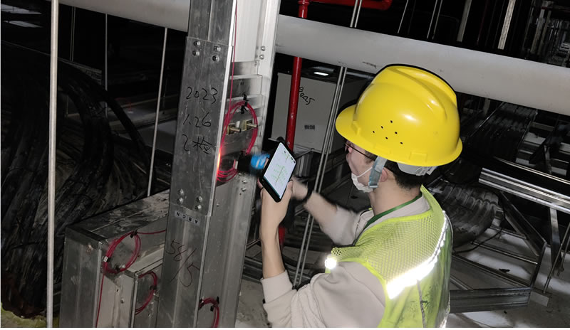
At each busbar connection, the temperature sensing optical fiber will be wound into a temperature measuring ring. The purpose of doing this is to more accurately monitor the temperature situation of these key parts. The optical fiber is directly fixed on the surface of the connection cover, usually coiled three times, and then fixed with high-temperature resistant tape. Considering the uniformity of wiring and subsequent calibration and debugging, the installation length of temperature sensing optical fibers at each connection should be consistent.
Fiber optic fixed position
The optical fiber should be firmly fixed on the upper surface of the busbar, as in most cases, this layout can more effectively capture temperature changes. Of course, if there are restrictions on the installation location, the optical fiber can also be fixed on the lower surface of the busbar according to the actual situation, but it is absolutely not allowed to fix the optical fiber on the outside of the side plate to avoid affecting the accuracy and stability of temperature measurement.
In the wider area inside the bus duct, S-winding can be used to lay optical fibers, which can increase the contact area between the optical fibers and the bus duct, and improve the sensitivity and accuracy of temperature sensing.
End processing
Each distributed fiber optic temperature measurement host can connect multiple channels of temperature sensing fibers, and a fiber optic terminal box is installed at the end of each channel fiber optic cable, with approximately 10 meters of fiber optic cable reserved inside the terminal box. The optical fibers inside the terminal box do not undergo temperature measurement and mainly serve the purpose of positioning testing.
(2) Data collection and processing
data acquisition
The distributed fiber optic host injects optical signal pulses into the fiber optic cable, and the post Raman scattering light generated during the transmission of the optical signal in the fiber optic cable carries temperature information. These optical signals will be reflected back to the fiber optic temperature measurement host. The host obtains temperature related data by receiving these reflected light signals.
data processing
After receiving the reflected light signal, the fiber optic temperature measurement host first performs photoelectric conversion to convert the light signal into an electrical signal. Lẹhinna, the electrical signal is amplified to enhance its strength for subsequent analysis. Afterwards, by analyzing the wavelength and frequency shift of the feedback, temperature data is calculated based on the relationship between Raman scattering and temperature. Ni akoko kan naa, the principle of optical time domain reflection positioning is used to determine the location of temperature anomalies.
(3) Temperature monitoring and alarm
Abojuto akoko gidi
The distributed fiber optic temperature measurement system can monitor the temperature changes along the bus duct in real time. On the monitoring interface of the system (such as the distributed fiber optic temperature monitoring system installed on the PC host), temperature data of the fiber optic cable laying line can be displayed in the form of temperature distribution curves, temperature variation curves of each point over time, ati be be lo., making it convenient for users to intuitively understand the temperature status of the bus duct.
Alarm settings
Users can set warning and alarm values based on actual situations. When the temperature exceeds the warning value, the system can issue a warning signal to remind the staff to pay attention to the temperature changes in the bus duct. When the temperature exceeds the alarm value, the system will emit stronger alarm signals, such as sound and light alarms, and can even notify relevant personnel through SMS and other means. Alarm types can include constant temperature alarm (alarm when a certain point reaches a specific temperature), regional temperature difference alarm (alarm when the temperature difference in a certain area is too large), rapid temperature rise alarm (alarm when the temperature rise speed is too fast), fiber breakage alarm (alarm when the fiber is broken), device abnormality alarm, ati be be lo. These alarms are visualized to facilitate users to quickly locate problems.

3、 Recommended equipment for distributed fiber optic measurement of bus duct temperature
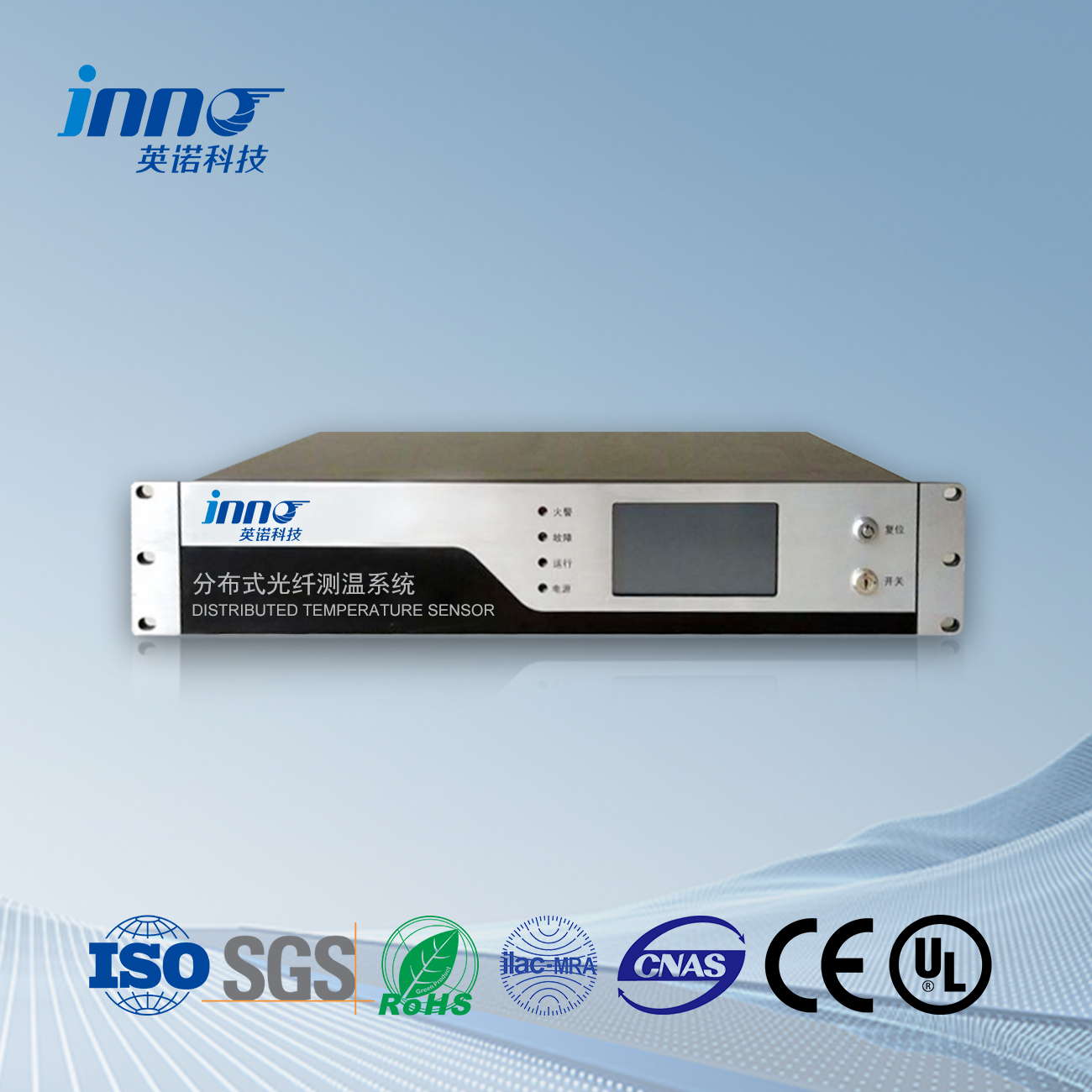
(1) Fuzhou Yingnuo Technology Distributed Fiber Optic Temperature Measurement System
System composition and functions
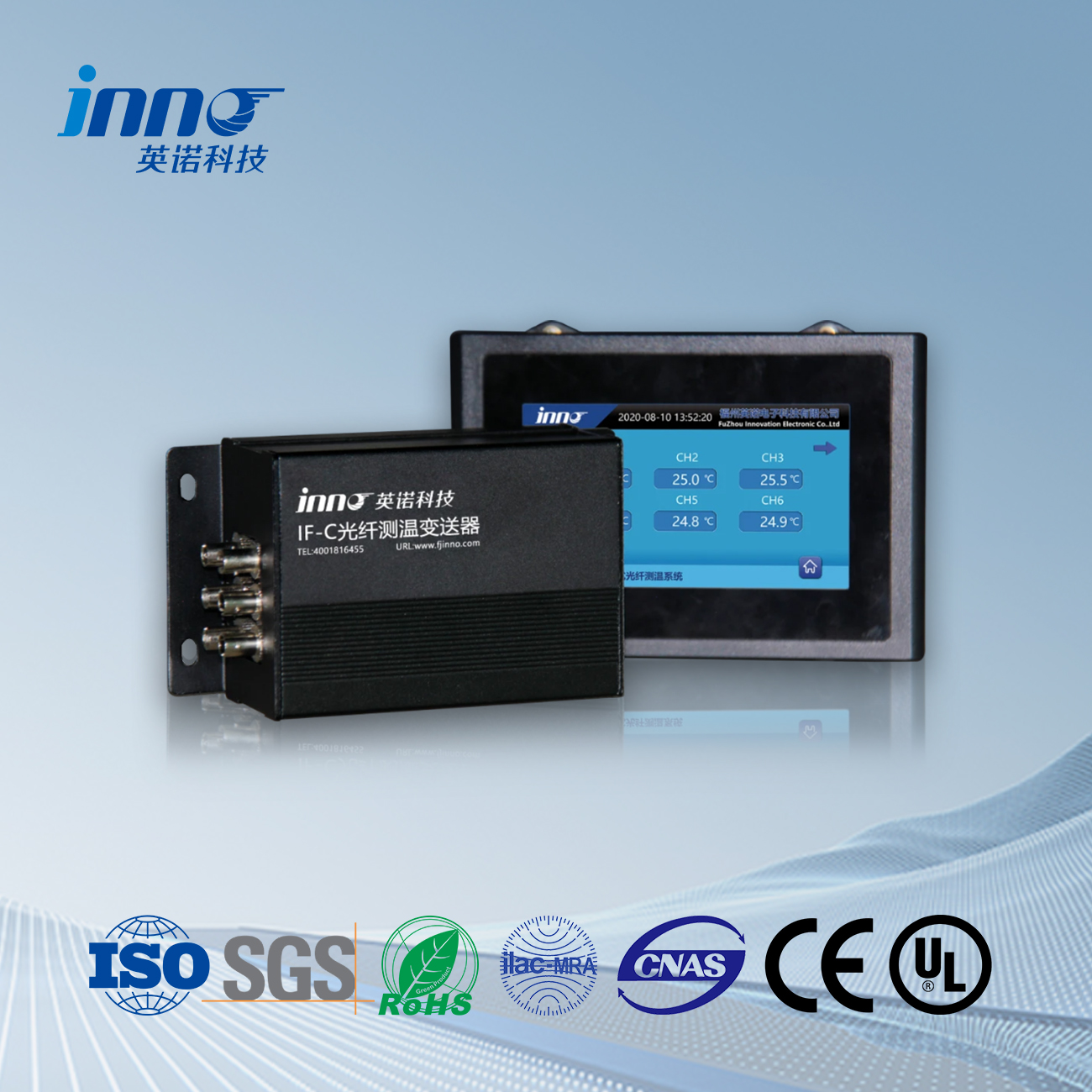
It consists of temperature measuring optical fiber, temperature measuring host, gateway, system platform and other parts. The temperature measurement host adopts M-class fiber optic temperature measurement host, which has good performance indicators. The communication management machine can upload the data of the fiber optic temperature measurement host to the system platform through the communication management machine.
Performance characteristics
This system has the characteristics of flame resistance, bugbamu resistance, ipata resistance, ga foliteji resistance, strong electromagnetic field resistance, radiation resistance, and strong anti-interference performance. It can accurately measure the temperature at various positions in the direction of temperature sensing fiber laying and locate temperature anomalies, and undertake functions such as signal acquisition, signal processing data analysis, over temperature alarm, and data transmission for the entire system. The temperature measurement accuracy of the system is high, reaching ± 0.05 ℃, and the positioning accuracy can reach 0.05m. Multiple optical fibers can be measured simultaneously, and according to actual needs, there are 4, 8, 12, ati 16 channels to choose from. And it can measure the temperature changes of the monitored object at every 1 mita (5 centimeters) point in real time.
(2) Power intensive bus duct DTS distributed fiber optic host
Host performance
The brand is Fuzhou Yingnuo Electronic Technology Co., Ltd., produced in Fujian, China. The continuous working time reaches 50000 wakati, and the model is fjnno.com. Installation methods include wall mounted, rack mounted, and cabinet mounted options. The temperature measurement range is (-200-700) ℃, and the maximum data processing rate is 4GByte/second. External display can be connected to an industrial computer via RJ45 Ethernet cable, or alternatively equipped with a 4.3-10 inch LCD screen to display temperature curves, temperature measurement cable construction quality, network information, equipment self check, equipment information display, alarm recording, equipment silencing and other functional units. The maximum measurement channel is 16 awọn ikanni (typical 4 awọn ikanni), which can be used to measure objects such as bus ducts, pipe gallery tunnels, epo ati gaasi pipelines, and also supports customized processing.

4、 Case study on distributed fiber optic measurement of bus duct temperature
Taking two commercial building projects as an example.
Project Akopọ
These two commercial buildings have a total construction area of over 10000 square meters, with 2 underground floors and 27 above ground floors, and are commercial office complexes. There are a total of 27 bus ducts with a total length of over 3600 mita, and approximately 1700 important monitoring points were surveyed on site.
Application of Distributed Fiber Optic Temperature Measurement System
This project applies a distributed fiber optic temperature measurement system. The 1m level fiber optic temperature measurement host and communication management machine are installed in the wall mounted box of the underground monitoring room, with a temperature sensing fiber length of 5500m laid along the surface of the bus duct. A circle of more than 1 meter is wrapped around the cover plate at the connection of the bus duct to ensure that each connector can measure the temperature of the cover plate.
System functions and effects
Alarm function: The system has visual alarm functions such as constant temperature alarm, regional temperature difference alarm, rapid temperature rise alarm, fiber breakage alarm, and device abnormality alarm. When the temperature of the bus duct is abnormal, an alarm signal can be promptly and accurately issued to notify relevant personnel for handling, avoiding the occurrence of safety accidents.
Display function: It can display the full range partition map, temperature distribution curve, and temperature variation curve of monitoring points over time. This allows the staff to intuitively understand the distribution of temperature in the bus duct and the trend of temperature changes over time, which is helpful for analyzing the operating status of the bus duct.
Query function: It can query and display historical data, and directly query device information, operating parameters, statistical information, ati be be lo. on the system diagram. Facilitating staff to analyze historical temperature data of bus ducts, such as analyzing temperature change patterns and identifying potential problems and hazards.
Analysis function: By displaying historical trends, evaluate future trends and provide maintenance reference information. This helps to develop a reasonable maintenance plan and prevent potential faults in the bus duct in advance.
Real time performance: The system monitors the temperature of the test area in real-time for 7 × 24 wakati, promptly detects and locates temperature anomalies, and achieves early warning. This is crucial for ensuring the safe operation of the bus duct, as the high voltage and current inside the bus duct can lead to serious safety accidents if the temperature is too high.
5、 Precautions for distributed fiber optic measurement of bus duct temperature
(1) Precautions during installation
Bus duct status
Before installing the distributed fiber optic measurement device, it is necessary to ensure that the bus duct is in a power-off state to avoid unnecessary accidents caused by current interference, while also ensuring the safety of the installation personnel.
Fiber optic fixation
The fixation of optical fibers should be stable and meet the requirements. If the optical fiber should be fixed on the upper or lower surface of the busbar according to regulations (in special cases), it cannot be fixed on the outside of the side plate. At the busbar connection, the optical fiber should be wound and fixed according to regulations to ensure that the installation length of the temperature sensing optical fiber at each connection is consistent, which helps to ensure the accuracy of measurement and subsequent calibration and debugging work.
Connection and wiring
When connecting equipment such as fiber optic terminal boxes, it is important to ensure a secure connection to prevent any looseness that may affect signal transmission. The wiring should be neat and reasonable, avoiding situations such as fiber compression and excessive bending. Ni akoko kan naa, the uniformity of wiring should be considered to facilitate subsequent maintenance and management work.
(2) Precautions during use
Temperature alarm setting
Users should set warning and alarm values reasonably based on the actual operation and design requirements of the bus duct. If the alarm value is set too low, false alarms may occur; If set too high, temperature anomalies may not be detected in a timely manner, leading to safety hazards.
Equipment maintenance
Regularly maintain the equipment of the distributed fiber optic temperature measurement system, including inspecting the temperature measurement host, fiber optic equipment, and other devices. Check the operating status of the temperature measurement host, such as whether data processing is normal, whether communication is normal, ati be be lo; Check whether the optical fiber is damaged, aged, ati be be lo., and replace or repair it in a timely manner if there are any problems.
Data monitoring and analysis
Regularly analyze the monitored temperature data, not only focusing on whether the current temperature value is normal, but also analyzing the trend of temperature changes. Fun apere, if it is found that the temperature in a certain area, although not exceeding the alarm value, shows a continuous upward trend, it also needs to be taken seriously and further checked.
Fiber opiti otutu sensọ, Ni oye monitoring eto, Pinpin okun opitiki olupese ni China
 |
 |
 |
 INNO okun opitiki otutu sensosi ,otutu monitoring awọn ọna šiše.
