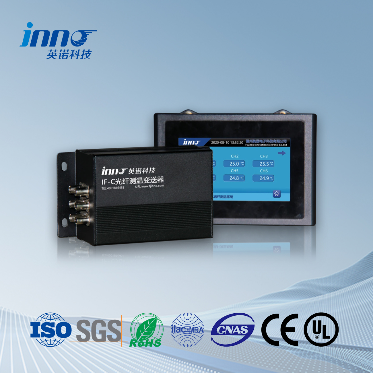
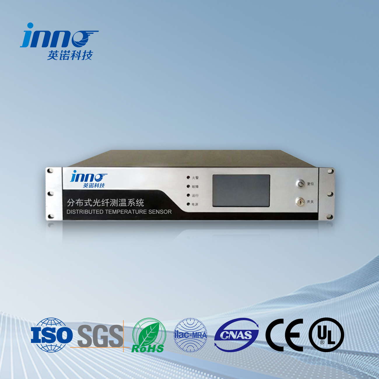
Understanding Fiber Optic Temperature Sensing Technology
Fiber optic temperature sensing utilizes specialized optical fibers to measure temperature variations along the entire length of the fiber. Unlike conventional point-based sensors, optical fibers can detect temperature at thousands of points simultaneously, creating comprehensive thermal profiles of transformer windings and critical components.
The technology leverages fundamental physical principles, primarily scattering phenomena that occur when light travels through optical fibers. As temperature changes affect these scattering patterns, sophisticated monitoring systems analyze the returning light signals to determine precise temperature measurements with accuracy levels previously impossible to achieve.
Key Operating Principles:
- Distributed Temperature Sensing (DTS) systems utilize Raman scattering to measure temperature continuously along the entire fiber length
- Fiber Bragg Grating (FBG) technology provides high-precision point measurements at critical locations
- Fluorescent fiber optic sensors emit temperature-dependent light signals that enable rapid response detection
Transformative Advantages Over Conventional Methods
The implementation of fiber optic temperature sensing systems delivers multiple operational benefits that directly address the limitations of traditional monitoring approaches. Electrical utilities have documented substantial improvements in transformer reliability, maintenance efficiency, and overall asset management following fiber optic system deployments.
| Performance Factor | Conventional Temperature Sensors | Fiber Optic Temperature Sensing |
|---|---|---|
| Measurement Points | Limited (typically 4-8 points) | Thousands of measurement points |
| Temperature Profile | Interpolated (estimated between points) | Continuous real-time profile |
| EMI Susceptibility | High interference vulnerability | Completely immune to electromagnetic interference |
| Early Fault Detection | Limited capability (often detects after damage occurs) | Can detect developing hotspots 3-6 months in advance |
| Response Time | Moderate (seconds to minutes) | Rapid (milliseconds to seconds) |
| Maintenance Requirements | Regular calibration needed | Minimal maintenance, self-calibrating systems available |
| Installation in Existing Units | Often requires shutdown and oil drainage | Can be retrofitted during routine maintenance |
The superior performance characteristics of fiber optic sensing technology translate directly into measurable operational benefits, including extended transformer lifespans, reduced maintenance costs, and significantly lower failure rates.
Implementation Strategies for Maximum Effectiveness
Successfully deploying fiber optic temperature sensing systems requires careful planning and coordination. Industry experience has demonstrated that following established best practices yields optimal results and ensures maximum return on investment.
Key Implementation Considerations:
Modern fiber optic temperature monitoring systems can be installed both during transformer manufacturing and as retrofits to existing units. For new transformers, manufacturers increasingly offer factory-installed options that integrate sensing fibers directly into winding structures during construction, ensuring optimal positioning and performance.
Retrofit installations require specialized expertise but can be accomplished during scheduled maintenance outages, often without requiring complete oil drainage. Strategic placement of sensing fibers focuses on high-risk areas including winding hotspots, cooling ducts, and core structures.
Integration with existing monitoring infrastructure typically involves connecting the fiber optic system to SCADA networks, allowing temperature data to flow into centralized asset management platforms. Modern systems support industry-standard protocols including IEC 61850, facilitating seamless data exchange with existing infrastructure.
Real-World Success: Eastern Power Utility Case Study
A major Eastern US utility implemented distributed fiber optic temperature sensing across its fleet of 35 critical substations transformers. The initial installation targeted their highest-risk assets—345kV GSU transformers approaching end-of-life status.
Within eight months of implementation, the system identified a developing hotspot in a 30-year-old transformer that conventional monitoring had missed entirely. The temperature anomaly showed a sustained 11°C differential compared to surrounding areas, indicating potential insulation degradation. Maintenance teams scheduled a controlled outage, confirmed insulation breakdown in its early stages, and performed targeted repairs.
Engineering analysis estimated that without early detection, catastrophic failure would have occurred within 3-5 months, resulting in approximately $2.8 million in replacement costs and an estimated $4.2 million in lost revenue during emergency replacement. The total implementation cost for the fiber optic system was $145,000, yielding an exceptional return on investment.
Emerging Trends in Fiber Optic Transformer Monitoring
The technology continues to evolve rapidly, with several emerging developments poised to further enhance transformer monitoring capabilities. Advanced manufacturers now integrate artificial intelligence algorithms with fiber optic temperature data, enabling pattern recognition that can distinguish between normal load-driven temperature fluctuations and developing fault conditions.
Edge computing integration allows for on-site processing of temperature data, reducing bandwidth requirements while enabling faster response to developing conditions. Some cutting-edge systems now incorporate hybrid sensing capabilities that measure multiple parameters simultaneously, including temperature, vibration, and partial discharge activity.
Quantum sensing technologies are showing promise in research settings, potentially enabling even greater sensitivity and spatial resolution in the next generation of fiber optic monitoring systems. These advances suggest that the capabilities gap between conventional and fiber optic monitoring will continue to widen in coming years.
Practical Implementation Guide
Four Essential Steps for Successful Deployment:
1. Risk Assessment and Planning: Begin by identifying your most critical transformer assets based on factors including replacement cost, operational importance, and existing condition assessment data. This prioritization ensures maximum initial return on investment.
2. System Selection: Evaluate available technologies based on your specific requirements. Consider factors including temperature range needs, spatial resolution requirements, and integration capabilities with existing systems.
3. Installation Strategy: Develop a detailed implementation timeline that aligns with planned maintenance outages to minimize operational disruption. For retrofits, work with experienced contractors who specialize in transformer fiber optic installations.
4. Data Integration Planning: Determine how temperature monitoring data will integrate with existing asset management systems. Establish clear alarm thresholds and response protocols to ensure operational teams can effectively utilize the enhanced information.
Following these structured steps has proven to maximize the effectiveness of fiber optic monitoring systems while minimizing implementation challenges across diverse utility environments.
Conclusion: The Future of Transformer Monitoring
Fiber optic temperature sensing technology represents a genuine paradigm shift in transformer monitoring capabilities. By providing unprecedented visibility into thermal conditions, these systems enable truly proactive maintenance strategies that were simply impossible with conventional approaches.
The documented benefits—including extended asset lifespans, reduced failure rates, and enhanced operational safety—deliver compelling economic justification for implementation. As the technology continues to advance and costs decrease, fiber optic temperature monitoring is rapidly becoming the industry standard for critical power transformers.
Forward-thinking utilities and industrial operators are increasingly viewing these systems not as optional enhancements but as essential components of modern transformer management strategies. The question is no longer whether to implement fiber optic monitoring, but rather how quickly the technology can be deployed across critical asset portfolios.
Additional Resources
- IEEE Power & Energy Society’s Transformer Committee Technical Reports
- CIGRE Working Group A2.37: “Transformer Reliability Survey”
- Electric Power Research Institute (EPRI): “Advanced Transformer Monitoring Technologies
- International Electrotechnical Commission Standards IEC 60076-2
Fiber optic temperature sensor, Intelligent monitoring system, Distributed fiber optic manufacturer in China
 |
 |
 |

