 INNO fibre optic temperature sensors ,temperature monitoring systems.

The fluorescent fiber optic temperature measurement system can be used for monitoring the temperature of the stator rotor, dry-type transformer, oil-immersed transformer, high-voltage switchgear contacts, and busbar inlet and outlet lines of generator sets, and has the characteristics of high voltage resistance and electromagnetic interference resistance.
1. Fiber optic temperature measurement for hydropower stations
Due to the fact that the main heating parts of the stator of a hydroelectric generator are located in various parts of the inner iron core of the stator. High stator voltage leads to increased iron loss; Or as the load current increases, the copper loss in the stator winding increases; Or the power factor decreases, and the rotor current increases over time; Unbalanced three-phase load current and other factors are all causes of stator temperature rise. When the temperature rises too quickly or reaches the warning value, if corresponding measures are not taken immediately, it will reduce the insulation performance of the insulation layer wrapped in the stator core or cause insulation breakdown, which is prone to problems and lead to malignant power outages. Therefore, it is necessary to achieve real-time online monitoring of the stator temperature of the water turbine motor. The fluorescence fiber optic temperature measurement system can achieve fiber optic temperature measurement of stator bars, stator iron core, upper and lower pressure finger fiber optic temperature measurement, busbar fiber optic temperature measurement, connection terminal fiber optic temperature measurement, rotor magnetic pole fiber optic temperature measurement, damping bar, and collector ring fiber optic temperature sensing online monitoring system, completely replacing the RTD platinum resistance scheme.
2. Fiber optic temperature measurement for box transformer
After years of operation, box transformers are prone to spontaneous combustion accidents under high loads. Due to the early stage of the transformer being in the blind spot of the main control monitoring, it could only be discovered by the main control personnel after the circuit breaker self ignition accident expanded and burned out, and the transformer tripped, resulting in severe equipment losses and significant economic losses on site. The box transformer fiber optic temperature intelligent monitoring system detects the temperature at different positions on the circuit breaker and the internal temperature of the transformer box through fluorescence temperature sensors, and transmits it to the main control background. The staff uses the data display unit to view the temperature monitoring information, and the data abnormal alarm unit monitors the data. When the data is unstable, the staff will be alerted, making it convenient for them to detect abnormal circuit breakers in a timely manner. Before the processor controls the switch to cut off the power supply urgently, the abnormal transformer box will be handled to avoid affecting the normal operation of the circuit breaker.
3. Generator fiber optic temperature measurement
Shortly after the operation of the generator, it was found that the temperature of the knife switch in the outlet fast switch cabinet of the generator was much higher than before under the same load situation. Therefore, the inspection of the fast switch cabinet was strengthened, and external forced cooling measures were taken. After coordination and shutdown inspection, it was found that the knife switch of the fast switch cabinet was not fully closed, causing the temperature of the knife switch to continuously increase. This time, the fiber optic temperature measurement system promptly reflected abnormalities, enabling us to promptly identify equipment hazards, take measures, and avoid damage to important equipment and accidents. Due to the installation of a fluorescent fiber optic temperature measurement system, the temperature of the switchgear busbar, contacts, and contacts has been monitored online, allowing for intuitive observation of temperature changes, timely detection of equipment hazards, timely adjustment of electrical loads, and avoidance of accidents.
Introduction to fiber optic temperature measurement system for motor stator and rotor
The temperature of the stator core, stator winding, and stator pressure index of a hydroelectric power station generator are important indicators that are of concern during generator operation. Their variation patterns reflect the degree of aging of the generator throughout its entire life cycle, and play a crucial guiding role in the operation and maintenance of the generator. Fiber optic temperature sensing technology is applied to measure the stator temperature of generators. Fluorescent fiber optic temperature measurement technology can accurately measure the internal temperature at different positions of the generator stator, and it also has many advantages such as insulation, high temperature resistance, corrosion resistance, electromagnetic interference resistance, and simple wiring. Compared with other temperature sensing technologies, fiber optic temperature sensing has many advantages such as corrosion resistance, electromagnetic interference resistance, low energy consumption, electrical insulation, and easy placement. The fiber optic temperature measurement technology based on Inno Technology is mature in use in hydroelectric power plant generators, and is suitable for using fluorescent fiber optic temperature measurement due to the comprehensive operating environment of the generator during hydroelectric power plant operation.
The principle of fluorescence fiber optic temperature measurement
By utilizing the luminescent properties of fluorescent materials, fluorescent substances are coated at the end of optical fibers. When the fluorescent substances are excited by certain wavelengths of light such as ultraviolet or infrared, they emit fluorescent energy. The energy generated by stimulated radiation of this fluorescent substance decays exponentially, and the decay time constant changes with temperature. The temperature of the measurement point can be obtained by measuring the decay time.
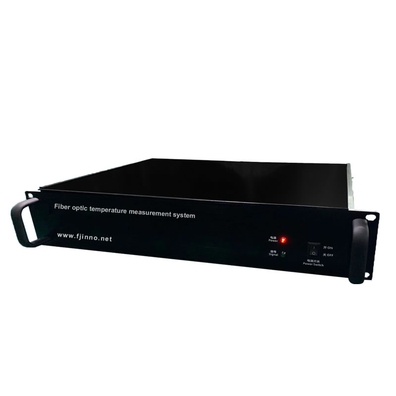
Characteristics of Fluorescent Fiber Temperature Measurement System
The fiber optic end probe is attached to the surface of the measured object to measure temperature
Temperature measuring optical fibers are immune to electromagnetic field interference
High voltage insulation, flame and explosion prevention
Single point temperature measurement and digital signal output
Fiber optic probes can reach a minimum of 600um
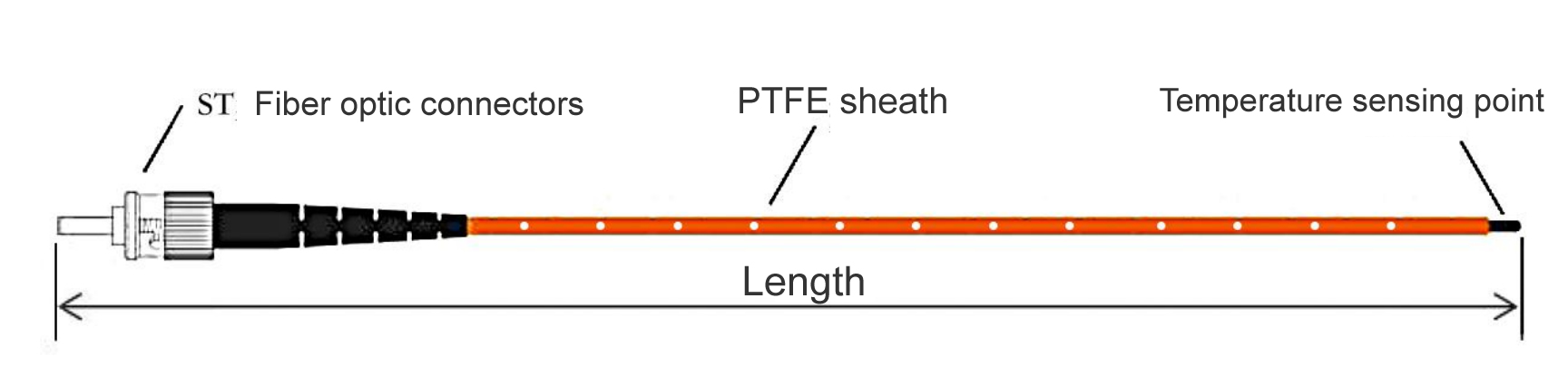
The fiber optic probe consists of three parts: ST connector, fiber optic cable, and end temperature sensing end. The ST connector is the connection part with the photoelectric module; Fiber optic cable is the transmission part, with quartz fiber inside. The quartz fiber has a coating and cladding on the outside, and a Teflon protective sleeve on the outermost part; The end temperature sensing end contains temperature sensing rare earth materials, which are used to generate optical signals containing temperature information; The optical fiber is resistant to high temperatures of 200 ℃ and has an outer diameter of 3mm. Long term bending radius of 13.2cm. Short term bending radius of 4.4cm. When the distance between the fiber optic lead and the ground is 0.4m, it can withstand a power frequency voltage of 100KV for a duration of 5 minutes


