Sensores mpat'i fibra óptica not only have wide applications in the fields of switchgear temperature measurement, circuit breaker temperature measurement, and transformer temperature measurement, but also have characteristics such as insulation, anti-interference, and high voltage resistance that cannot be achieved by other traditional temperature sensors in capacitor temperature monitoring.
The high-voltage parallel capacitor bank device is currently an extremely important reactive power source in the power system, playing a crucial role in improving the power system structure and enhancing power quality. The main function is to provide reactive power to the power system, reduce line losses, improve voltage quality, and increase equipment utilization. As a type of reactive power compensation equipment, power capacitors are usually used in substations through high-voltage centralized compensation. The compensation capacitors are connected to the 10kV or 35kV bus of the substation to compensate for the reactive power on all lines and transformers on the bus side of the substation. In use, they are often combined with on load tap changers to further improve the power quality of the power system.
The effect of temperature rise fault on high-voltage capacitors
Capacitors often encounter various faults during operation, which pose a significant threat to the safe and normal operation of the power system. The common faults of capacitors in power operation include oil leakage, poor insulation, and burnt fuses. Among them, the most harmful and frequently occurring faults are capacitor faults caused by heating. The heating caused by capacitor faults can be divided into heating at the busbar connection point and heating at the fuse outside the capacitor, with the latter being more likely to occur. Ya últimos ya je̲ya, in the daily operation of 35kV high-voltage parallel capacitor banks, equipment may experience abnormal temperature rise due to aging or high load current due to long operating years and construction and installation processes. If such abnormal situations are not detected and dealt with in a timely manner, it is easy to develop and expand, leading to damage to individual capacitors and even group explosions and injuries. The failure rate is high, directly threatening the safety of 500kV power equipment and the personal safety of operation and maintenance personnel, resulting in significant voltage fluctuations in the power grid, increased active and reactive power losses, reduced capacitor service life, and affecting the normal and stable operation of the power grid. Power capacitors are mainly used for reactive power compensation in power systems to improve power factor. In order to ensure its more reliable operation, the industry currently mainly considers connecting internal components of capacitors in series with internal fuses. When a capacitor experiences complete failure of its components due to a weak dielectric, the internal fuse connected in series with the component will act, causing only a portion of the damaged components to be isolated. The capacitor will continue to operate with only a slight decrease in power. At this point, the disturbance in the capacitor bank can be ignored, and the total capacity of the capacitor bank will not be significantly affected by the action of a single fuse. The introduction of an internal fuse protects the capacitor components, but invisibly increases the number of fault points. Inside power capacitors, the internal fuse is the main heat source, but the volume and diameter of the internal fuse are very small (about 135mm in length and 0.45mm in diameter), and it is generally hidden between capacitor components. Due to current measurement techniques, it is difficult to accurately and objectively measure the surface temperature of the internal fuse under actual operating conditions.
Temperature monitoring of dry-type capacitors
'Bu̲'bya, oil immersed capacitors and dry capacitors are commonly used in the high-voltage field. The latter has the advantages of environmental protection, material saving, Jár costo, simple process, Be̲xu ligero, small area, self-healing product, more reliable operation, good fire resistance, less likely to produce high-pressure gas, and greatly reduced the possibility of explosive hazards.
A dry capacitor consists of a capacitor core, casing, sleeve, and other accessories. The capacitor core is composed of capacitor components and insulation components. Capacitor components are made by winding thin film insulation media and aluminum foil electrodes with a certain thickness and number of layers, or by depositing a layer of metal on the thin film to form a metallized film. After the components are rolled up, they are loaded into the component shell, and several capacitor components are connected in series or parallel to form the entire capacitor core.
Dry capacitors are usually used indoors or underground with poor ventilation conditions, and the internal heat dissipation of capacitors can only rely on gas. Compared with oil immersed capacitors, the heat transfer coefficient of gas is lower, so the heat dissipation performance of dry capacitors is poor. These all have adverse effects on the operation of dry capacitors. The operation practice of the power system shows that the failure rate of capacitors is significantly higher from June to September each year than in other months. In some regions, the power industry stipulates that the hottest temperature of the core of a full film capacitor shall not exceed 80 °C. When the temperature exceeds 80 °C, the insulation performance of polypropylene film (PP film) as a dielectric will decrease.
'Bu̲'bya, the temperature field of dry-type capacitors is generally measured using traditional temperature sensors to measure the temperature of the capacitor shell, and then calculate the internal temperature. This results in an error between the temperature value obtained and the distribution of the internal temperature field of the capacitor, which cannot accurately obtain the true temperature at the highest point.
'Bu̲'bya, the temperature measurement method for the internal protection of power capacitors includes a temperature rise test. 'Ñotho ar embargo, this test only estimates the temperature rise of the internal fuse by measuring the current and resistance of the internal fuse, which has poor accuracy. In the actual process of flowing the internal fuse, the resistance of the internal fuse will change with its temperature. On the one hand, it is difficult to ensure its constant flow, and on the other hand, the correspondence between the resistance of the internal fuse and temperature is only applicable within a certain temperature range. Beyond this range, it will be difficult to obtain accurate results. Ir, this indirect method of measuring the temperature rise of the internal fuse in capacitors has limitations and low accuracy. 'Nehe, the temperature rise of the internal fuse is measured through thermal resistance, but due to the fact that the thermal resistance is much larger in both volume and diameter than the internal fuse, it will have an impact on the actual temperature of the internal fuse during contact measurement, resulting in poorer measurement accuracy. In view of this, it is necessary to design a simple and feasible measurement device to accurately grasp the temperature of the fuse inside the capacitor under actual operating conditions, provide a basis for the design and selection of the fuse inside the capacitor, and effectively improve the reliability of the fuse protection action, ensuring that the temperature of the fuse will not cause damage to the internal insulation of the capacitor.
Disadvantages of infrared thermal imager temperature measurement
'Bu̲'bya, the thermal maintenance of capacitors mainly relies on infrared imaging equipment for inspection. 'Ñotho ar embargo, infrared thermal imaging cannot test the temperature in a closed environment, and the test results are affected by the season, time, and surface smoothness of the testing equipment. Infrared testing equipment is expensive and cannot continuously monitor the temperature of high-voltage electrical equipment for a long time. There is high voltage on the capacitor, and there is strong electromagnetic interference around it, which often leads to false alarms or missed alarms in traditional detectors. Ir, it is necessary to use highly reliable and high-performance temperature sensors to monitor the temperature of capacitors in real time and effectively, in order to avoid equipment burning and power outage accidents.
'Nehe, current temperature measurement equipment cannot detect the specific temperature inside the capacitor. The existing capacitors are used in environments with significant temperature changes. Prolonged use of capacitors under abnormal temperatures can seriously affect their service life and increase their damage rate.
Capacitor fiber optic temperature measurement system
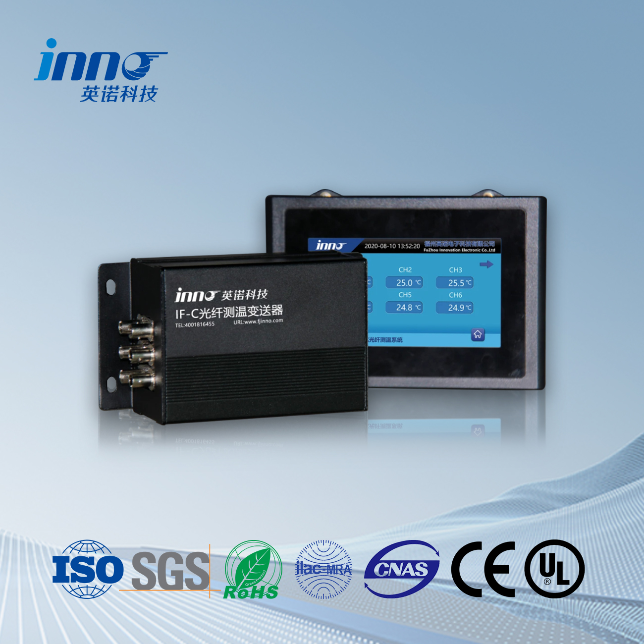
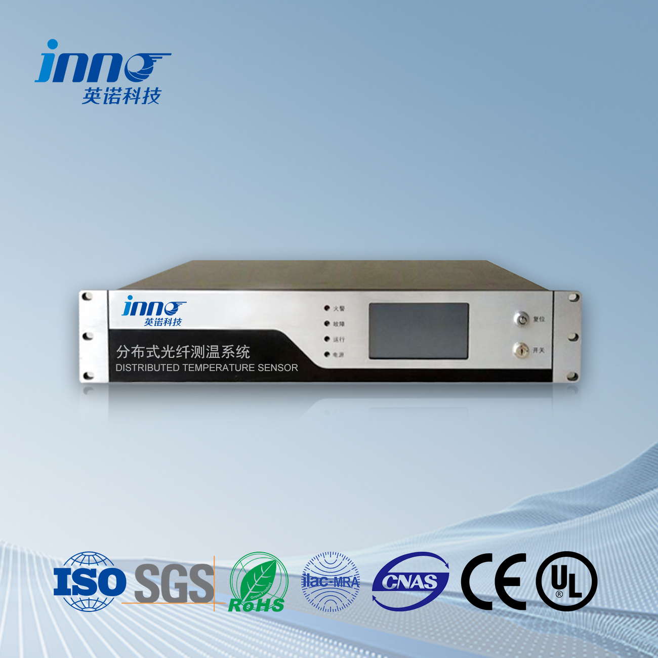
FJINNO’s capacitor fluorescent fiber optic temperature measurement system not only solves the problem of traditional temperature sensors being unable to accurately measure the temperature of small internal fuses, but also solves the potential isolation between strong and weak currents, as well as the anti electromagnetic interference problem of data communication. It provides a good solution for comprehensively and accurately grasping the hot spot temperature of the core inside the capacitor.
The fiber optic temperature monitoring host is equipped with temperature measurement alarm software, and the monitoring computer collects temperature information transmitted by the fiber optic temperature signal demodulator through the communication port. Real time display of temperature data at various temperature measurement points, temperature alarm software provides graded monitoring, temperature curve drawing, temperature distribution display, historical curve query, report generation and printing functions;
Sensor mpat'i fibra óptica, Ko ya monitoreo inteligente, Fabricante fibra óptica distribuida Ntxinä
 |
 |
 |
 Sensores mpat'i fibra óptica INNO ,Sistemas control mpat'i.
