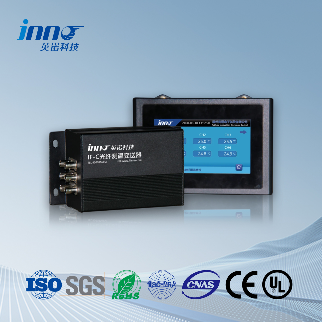
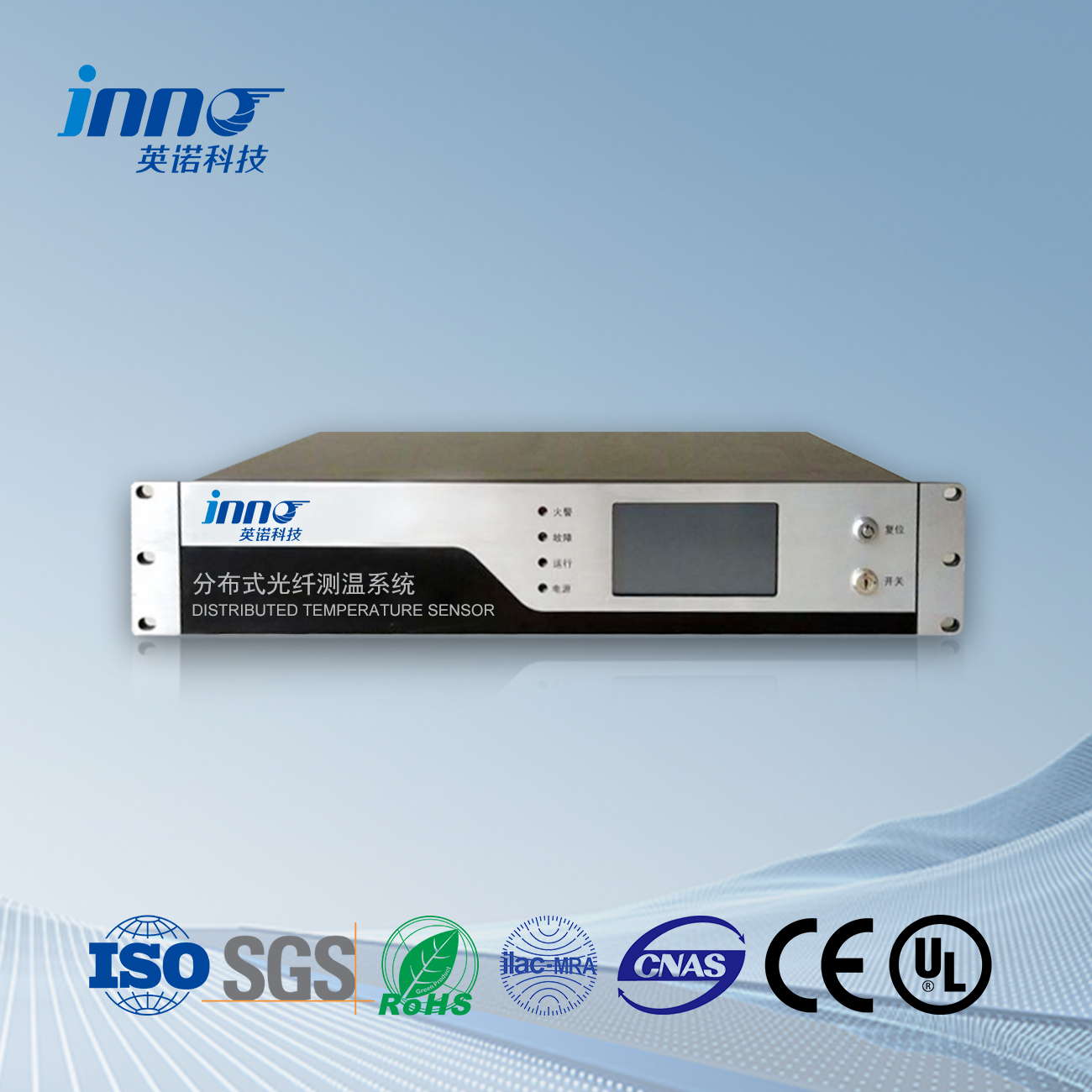
Power cable fault location monitoring device, altitude: ≤ 3000m.
ambient temperature
Maximum temperature:+45 °C;
Minimum temperature: -25 °C;
Maximum daily temperature difference: 25K.
Wire temperature
Maximum temperature:+100 °C;
Minimum temperature: -40 °C.
Solar radiation intensity: 0.1W/cm2 (wind speed 0.5m/s) (outdoors).
Seismic resistance capability
Seismic intensity: 8 degrees;
Ground horizontal acceleration: 0.25g;
Ground vertical acceleration: 0.125g;
The seismic wave is a sine wave with a duration of three cycles and a safety factor of 1.67.
humidity
5% to 100% RH.
atmospheric pressure
550hPa to 1060hPa.
Polluted conditions
Pollution level: Level E;
The installation site is located in an outdoor area within 1km of the coast, with a salt density greater than 0.25-0.35mg/cm2;
The shell materials, bolts, and protection levels of sensors, high-frequency cables, acquisition boxes, and terminal boxes should meet the requirements of corrosion resistance, and serious rusting should not occur during operation.
wind speed
The monitoring device should operate normally under gusts of ≤ 45m/s.
safety requirements
Comply with the relevant regulations in GB4943 and the Class B security regulations in GB9361 for computer rooms.
Werkende voeding
Rated voltage: Wisselstroom 220V 15%;
Frequency: 50Hz;
Harmonic content:<5%.
Ice thickness
10Mm (outdoor).
When the device operates in harsh natural environment such as wind, rainstorm, freezing and strong electromagnetic environment, its working stability and reliability shall not be significantly affected.
The connection of the monitoring device should not change the electrical connection method of the monitored cable body, and should not affect various performance indicators such as sealing performance, insulation performance, and mechanical performance.
The sensor should be able to withstand the rated operating voltage, operating overvoltage, and impulse overvoltage specified in GB/T 7674.
The sensor housing should be reliably grounded, and the output terminal of the sensor should have voltage limiting protection function. The no-load output voltage should not endanger personal safety.
The installation of monitoring devices should meet the following requirements: sufficient safety distance from nearby high-voltage live parts and areas; Effective protection against lightning, overvoltage and ground potential rise caused by switch operation; No safety hazards related to power supply, electromagnetic compatibility, and network communication, and no impact on the safe operation of other systems.
Basic requirements for monitoring devices
The device should meet the requirements of modularity and standardization, and reserve sufficient channels to facilitate the expansion of data acquisition units and sensors, supporting hot plugging and interchangeability requirements.
The on-site signal acquisition control unit and monitoring host should use reliable dedicated power supply.
The device should have an on-site verification and testing interface to facilitate users in conducting on-site debugging and testing.
The device should have overcurrent and lightning protection functions.
The device box should have anti-theft lock function, and the anti-theft lock should use passive electromagnetic lock.
The monitoring range of the device is from above the outdoor cable terminal to below the GIS terminal.
Basic requirements for monitoring system software
The supporting software of the monitoring device collects the propagation time of transient traveling waves between the fault point and both ends of the power cable at the time of defects and faults, and calculates the distance between the fault point and either end of the cable online. The front-end data processing device obtains the signal and transmits it to the data receiver. After passing through the data receiver to the host, the back-end host receives the data and performs waveform diagnosis and analysis to finally determine the location of the fault point. The positioning error is L * 0.5%+5m (L is the cable length).
Accurate positioning of power cable faults only requires installing a set of monitoring terminals at each end of the cable; If the cable has a T-junction, a set should be installed on each section of the cable’s T-junction to achieve precise positioning in case of cable T-junction faults. The on-site monitoring terminal is fixedly installed near the grounding box of the cable terminal cover, and the sensor is mounted on the cable body and grounding wire. Each set of precise fault location device for power cables includes a monitoring terminal and one set of sensors for each of phases A, B, and C; Each set of sensors includes a traveling wave sensor and a power frequency current sensor. The monitoring terminal includes core units such as power module, communication module, time synchronization module, and data processing module.
The data transmission adopts wireless/wired methods. If wireless transmission is used, the monitoring data is processed by the front-end data processing unit using a wireless APN private network (including 4G/5G, enz.), which meets the requirements of Q/CSG1205031-2020 “Transmission Line Online Monitoring Communication Protocol and Information Interaction Specification (Trial)”. The winning bidder shall assist in the implementation of the monitoring data access cable online monitoring platform for the bidding products, including data access development, system software system release, and on-site services.
The software can automatically perform online monitoring and diagnostic analysis on the fault waveforms of cable line tripping collected by on-site monitoring terminals. The backend software collects monitoring data in real-time for a long time and establishes historical data files, and plots these data into various curves. Cable operation and maintenance personnel can understand the long-term operation status of the entire cable based on the information provided by these curves. Op hetzelfde moment, the software processes the collected current data and provides device status alarms, cable current abnormality alarms, and cable fault alarms. And promptly notify the operation and maintenance management personnel of the diagnosis results through web terminals or SMS. Enable line operation and maintenance personnel to constantly monitor the operation status of cables, promptly warn of cable faults, and quickly locate the fault point after the fault occurs.
Functional requirements for monitoring system software
Cable fault interval positioning
For hybrid overhead cable lines, it is possible to determine whether the fault is located in the cable section or the overhead section.
Accurate positioning of cable faults
After a cable fault occurs, it can quickly and accurately locate the location of the cable fault point.
Dual end traveling wave fault location function
Realize automatic dual end positioning; Realize manual input of dual end start time positioning; The initial arrival time of the fault wavefront can be manually corrected.
Communication function
Support wireless APN/wired communication methods, capable of receiving defect and fault transient traveling wave data from the station end traveling wave acquisition device; Can manually and automatically retrieve station data; Communication parameters can be configured.
Data management function
Implement configuration data management; Implement fault record data management; Data import and export: You can import and export configurations or fault records separately.
Functional requirements for monitoring devices
data acquisition
The monitoring terminal can automatically monitor, collect, and store waveform data such as fault tripping traveling wave current of cables;
Clock synchronization
On site monitoring terminals should use reliable methods to maintain accurate clock synchronization between the traveling wave acquisition devices at both ends of the cable, and ensure that the clock error of the two devices does not exceed 20 ns during the sampling time of the pulse waveform at the time of fault.
data communication
The monitoring terminal can send real-time data (such as fault traveling waves) and device heartbeat information collected in accordance with the message format specified in Q/CSG1205031-2020 “Transmission Line Online Monitoring Communication Protocol and Information Interaction Specification (Trial)”, and send them to the backend system center station through APN private network wireless/wired network communication; The monitoring terminal can automatically save the collected monitoring data in case of communication interruption, and promptly transmit the stored data back to the central station after the terminal communication is restored; Cable fault traveling wave messages have priority for transmission.
Equipment self check and self recovery function
The device should have a self detection function, providing timed self check information on the device’s operating status, recording fault logs, and the detection cycle can be set. The device should have a self recovery function. In the event of abnormal power supply termination or other situations, the device should be able to automatically resume normal operation without losing stored data.
Anti interference function
It should have the ability to effectively suppress and eliminate background interference in complex electromagnetic environments on site, and anti-interference technologies such as filtering, shielding, identification, and positioning can be used to ensure the effectiveness of monitoring.
Structure and appearance
The installation of online monitoring devices should pay attention to safety and aesthetics, and wiring should have cable trays or protective sheaths; The installation of sensors does not affect the daily testing and maintenance of cables; The terminal box should be tailored to local conditions, and the location of cable laying in the substation needs to be approved by the substation operation unit.
Local signal devices should reserve interfaces for live testing.
The monitoring unit should be protected by a stainless steel chassis, which can be opened flexibly and matched tightly. There should be no dust or debris inside the chassis. The interior of the chassis requires moisture resistance.
The chassis should take necessary measures to prevent electromagnetic interference, and the exposed conductive parts of the chassis should be electrically connected and reliably grounded.
The surface of the chassis should not have mechanical damage, scratches, cracks, or deformation. The external coating and electroplating layer should be firm, uniform, and smooth, without peeling or rusting. The chassis should be made of 304 stainless steel material.
The bottom plates, baffles, and components inside the cabinet should be firmly fixed without burrs, the bolts should be flat, and the control components such as keyboards and buttons should be flexible. The display and markings on the panel should be clear.
The electrical and communication cable lines are firmly connected, with a reasonable and beautiful direction. Each connecting sleeve is labeled, and the exposed parts of each welding point are covered with heat shrink tubing. The power supply incoming line is labeled with a strong current sign.
Both the exterior and interior of the device should be designed with flame retardant, explosion-proof, anti-corrosion, moisture-proof, enz. The hardware of the device should use industrial grade or above components.
The power and signal sockets should use waterproof aviation plugs and have anti misoperation design; The device should have a structural design that is easy to lift and transport.
Power supply method
The precise positioning device for cable faults adopts CT induction power supply/mains power/station power supply as the main power supply method, and solar power supply can be used as an auxiliary power supply method.
Glasvezel temperatuursensor, Intelligent bewakingssysteem, Gedistribueerde fabrikant van glasvezel in China
 |
 |
 |
 INNO glasvezel temperatuursensoren ,Temperatuur Monitoring Systemen.
