 INNO फायबर ऑप्टिक तापमान सेन्सर ,तापमान निरीक्षण प्रणाली.
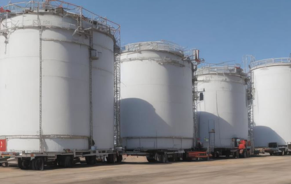
Most fire accidents are caused by high temperatures. In the petroleum and petrochemical industry, oil tank areas are a major industrial hazard. High temperatures in large oil storage tanks can lead to oil volatilization, fires, and even explosions, causing significant casualties and property damage. सध्या, the alarm data of commonly used oil tank fire automatic alarm systems comes from the fiber Bragg grating temperature measurement system TBG. This type of sensor can only perform scattered measurement. त्याच वेळी, during installation, it is necessary to drill holes and weld on the oil tank wall panel or directly input it into the tank to measure the temperature of liquids and gases, which is inconvenient for both early construction and later maintenance. On this basis, the वितरित फायबर ऑप्टिक temperature measurement system DTS can be applied to monitor the temperature during a smoldering fire (generating a small amount of smoke and heat), issue warnings, and give on-site operators sufficient time to take corresponding measures to avoid accidents or fires. त्याच वेळी, it can effectively improve the automation level of enterprise safety management.
Principle of Distributed Fiber Optic Temperature Measurement System
The main working basis of the वितरित फायबर ऑप्टिक तापमान मापन प्रणाली is the principle of optical time-domain reflectometer (OTDR) and the temperature effect of backward Raman scattering in optical fibers.
The OTDR principle is mainly used for fiber optic positioning, which can achieve spatial distributed positioning of the temperature field inside the oil tank, determine the loss of various parts of the fiber optic (including damaged points), and locate temperature measurement points.
Backward Raman scattering effect refers to the phenomenon where when a laser source in the main processing unit injects a pulse signal with a wavelength of 905nm into a fiber, although the propagation speed of light is fast, it still has a certain degree of attenuation. Some scattered light will propagate in the opposite direction of the incident light, and the Raman signal contained in the scattered light carries temperature field information. This signal is processed through a digital signal processing system (DSP) to provide information about the temperature field distribution of the storage tank and output a temperature distribution map on the entire fiber.
Design of Distributed Fiber Optic Temperature Measurement System
The distributed fiber optic temperature measurement system must ensure the following three points: it can provide early detection of oil tank fire hazards; Can clearly indicate fire hazard locations; Send fire information to the fire alarm control system, activate the emergency control system, such as closing the emergency shut-off valve, cutting off oil pipes, and other emergency operations.
The layout of the equipment must be combined with the structural characteristics of the oil tank, taking into account comprehensive coverage and convenient installation. The entire control system is divided into automatic control and manual control according to the requirements of the fire alarm control system, and manual control is given priority. Automatic control: Once the temperature value of the measured oil tank exceeds the standard set alarm temperature, the distributed फायबर ऑप्टिक तापमान देखरेख प्रणाली sends real-time fire alarm data to the fire alarm host. The alarm host receives a relay action monitoring signal and confirms it as a fire alarm through logical judgment system. Manual control: once a person finds a fire and the alarm system has not been started, he can press the emergency manual alarm button. The fire alarm host receives the button alarm signal, the system confirms that it is a fire, and immediately enters the fire treatment program. The alarm host will then send an audible and visual fire alarm to the relevant areas and display it. त्याच वेळी, it will link the corresponding fire hydrant system, automatic foam spray system, इ., and upload the alarm signal to the oil depot management office, so as to organize personnel evacuation and rescue work in a timely manner.
The entire monitoring system consists of a DTS control unit, temperature sensing optical cables, and fiber optic connectors, which can be linked with other systems to form a fire alarm control system,
DTS control unit
The DTS control unit is debugged and programmed by authorized personnel in the human-machine interface environment through an engineer station. The area length and alarm points can be set according to needs, and the temperature trajectory of the optical cable can be displayed in real time on the PC. The alarm signal can be highlighted, including the determination of the actual location of the damaged point of the optical cable. The area setting and alarm point position can also be changed as needed. त्याच वेळी, the entire temperature measurement system can be interconnected with other control systems through relay outputs and perform logical judgments. In fire protection applications, it can be connected to the fire alarm control host to provide signals for sound and light alarms, with accurate and complete signal output; The DTS control unit can directly output signals to various digital display devices, such as central control room projectors, displays, इ., and can set information sharing permissions based on the sharing level.
Temperature sensing detection optical cable
The temperature sensing fiber optic cable is the front-end device of the entire system, directly related to the judgment results of the DTS control unit. It can be installed on the outer wall of the oil tank. The alarm detection logic judgment for each zone can use any combination of three methods: maximum temperature in the zone (constant temperature), temperature rise rate in the zone (differential temperature), and the difference between the maximum temperature in the zone and the average temperature in the zone (uniformity of zone temperature) to ensure early and reliable alarm and prevent smoldering. त्याच वेळी, considering that the layout of oil tank areas is often in harsh environments, temperature sensing detection optical cables should have good characteristics such as anti biting, earthquake resistance, गंज प्रतिकार, इ. The optical cables should have a sturdy sheath (PVC flame-retardant material), which can provide good protective characteristics. त्याच वेळी, they should also provide good temperature conductivity to ensure that fires can be detected quickly. The longest detection distance for a single channel is 30KM, and the number of channels can be expanded to 16. The positioning accuracy can reach ± 0.5m. The fastest response time for a single channel is 3.5s, and the startup preheating time is instant use.
The attenuation of the entire system optical cable shall not exceed the standards of the DTS control unit. The maximum attenuation rate on the 2km optical fiber shall not exceed 10dB, each junction box shall not exceed 0.4dB, and each fusion joint shall not exceed 0.2dB.
Fiber optic connecting devices
The fiber optic connecting device serves as the hub for connecting the temperature sensing detection optical cable to the DTS control unit. The tail fiber and the detection optical cable are connected through fiber optic fusion points, which are located in the fiber optic connection box next to the DTS control unit.
Distributed fiber optic fire detection system
According to the design requirements, there are a total of 4 external floating roof crude oil tanks and 5 internal floating roof finished oil tanks in the oil tank area, which are equipped with fiber optic fire detection systems. Install a fiber optic temperature fire detector at the sealing ring of the floating plate of the floating roof tank, and add twice the vertical laying length. The required detection optical cable for winding a oil tank is about 196m. Based on the above data calculation, taking 1.15 times the effective redundancy, the required optical cable for the storage tank is 2028m.
Based on the distribution characteristics of oil tanks and specific requirements for temperature monitoring, this project adopts a “one tank, one machine” mode for design. त्याच वेळी, to increase system stability, dual machine hot standby is adopted, which can automatically switch in case of system failure. A total of 9 fiber optic distributed temperature monitoring systems are used to monitor the required oil tanks in real-time online.
1) Each tank is monitored by an independent sensing optical fiber, which is installed on the floating plate of the tank and at the outer edge of the secondary sealing ring.
2) The anti-static optical fiber led out by the फायबर ऑप्टिक तापमान सेन्सर installed on the floating plate inside the tank is protected by laying an explosion-proof metal hose with a diameter of DN25 inside the tank. The upper end of the explosion-proof metal hose is fixed on the flange of the manhole on the top of the tank, and the lower end of the metal hose is fixed on the floating plate inside the tank. The fixing method is non hot work, and the explosion-proof metal hose is equipotentially connected to the tank body.
3) Considering the changes in displacement at the top of the floating roof tank, in order to prevent the anti-static optical fiber passing through explosion-proof metal hoses from malfunctioning due to dragging, the reserved length should not be less than 0.5 times the height of the outer wall of the tank, and a disc optical fiber device should be used to control the anti-static optical fiber in a certain position area.
4) The anti-static optical fiber led out by the fiber optic temperature sensor installed on the floating plate inside the tank is threaded through an explosion-proof galvanized pipe with a diameter of DN25 on the outer section of the tank and led along the escalator or tank wall to the existing ground trunking. It is connected and protected with the communication optical cable installed inside the trunking through a waterproof optical cable splice box, and the elbow part is connected with an explosion-proof metal hose.
5) All fiber optic temperature sensors installed on the floating roof of each oil tank in the tank area are led out through anti-static optical fibers and converged to communication optical cables for signal collection and transmission to the monitoring room. The communication optical cable is laid directly buried, and the elbow is connected with explosion-proof metal hose.
6) After the communication optical cable is transmitted from the tank area to the monitoring room, it is connected to the detection channel interface corresponding to the DTS host through a short distance fiber optic tail with a standard fiber optic connector, which is a fiber optic jumper.
7) Nine 2-channel DTS distributed fiber optic temperature measurement hosts were placed in the monitoring room to achieve temperature signal acquisition, temperature rise warning, तापमान अलार्मपेक्षा जास्त, fault detection, and information management operations for the fiber optic temperature sensors installed on the oil tank site. They can be connected to the fire alarm control system through the switch alarm interface to achieve fire alarm and display it in the fire duty room. The current temperature value, alarm status, and historical temperature curve of all temperature sensing points of the storage tank can be visually displayed in the instrument operation room through the electronic map of the configuration software. An external sound and light alarm can also provide alarm signals in the instrument operation room.
The distributed fiber optic temperature measurement system can detect the temperature value at every point along the fiber optic cable in real-time online, and can determine the trend of fire spread; Multiple alarm methods such as temperature difference and temperature rise rate can be set, and multi-level warnings can be set up to achieve early warning before a fire occurs; Alarm zones can be set arbitrarily according to changes in on-site conditions, and each zone can set different alarm values; It can withstand harsh environments, resist electromagnetic interference, and does not generate electromagnetic radiation. The effective lifespan of the detection optical cable is 30 वर्षे, overcoming the high false alarm rate and maintenance difficulties of the point type fiber optic grating temperature measurement system. It has reference significance for the fire safety of future oil tank areas.
फायबर ऑप्टिक तापमान सेन्सर, बुद्धिमान निरीक्षण प्रणाली, चीनमध्ये वितरित फायबर ऑप्टिक निर्माता
 |
 |
 |
