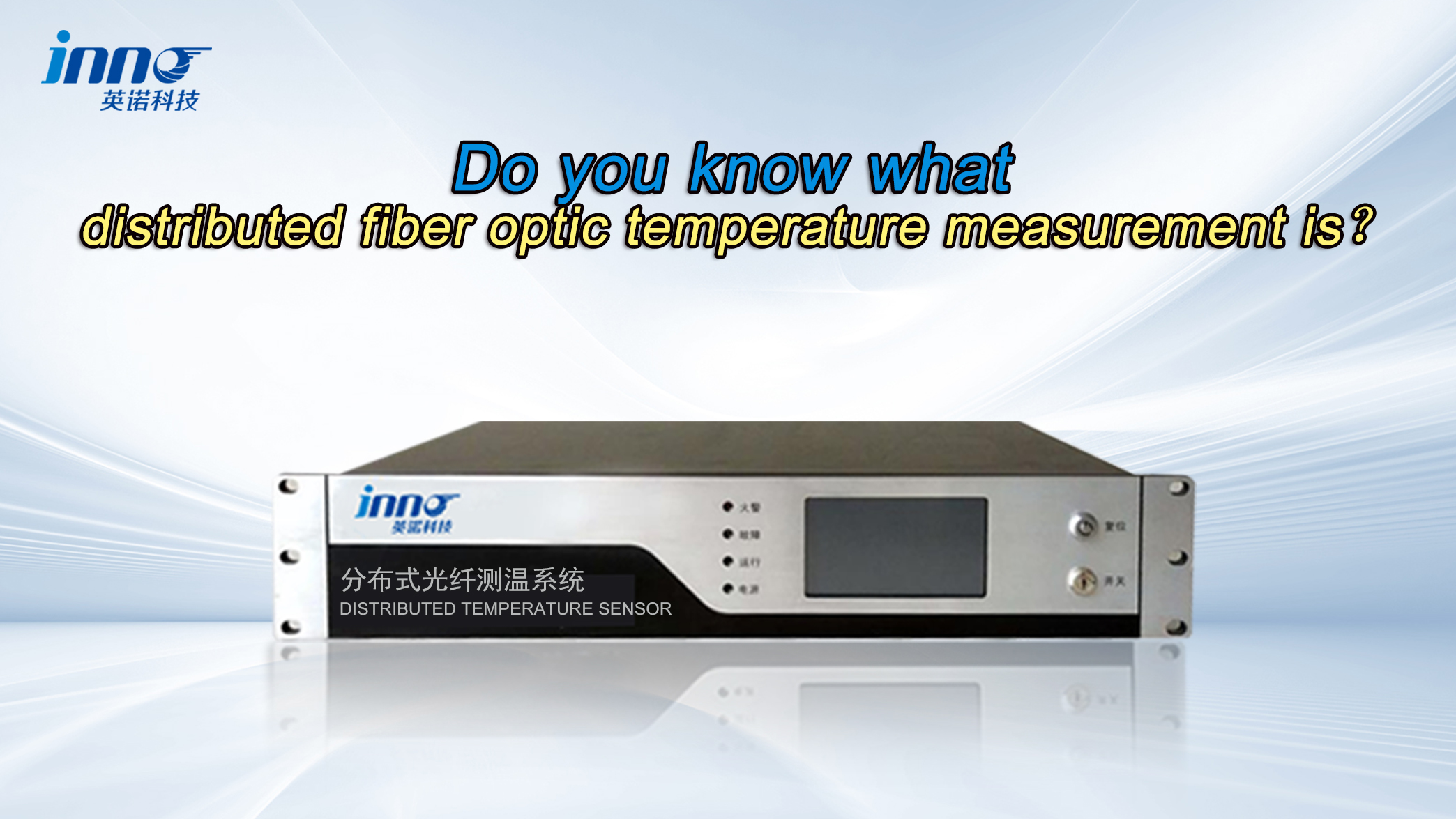
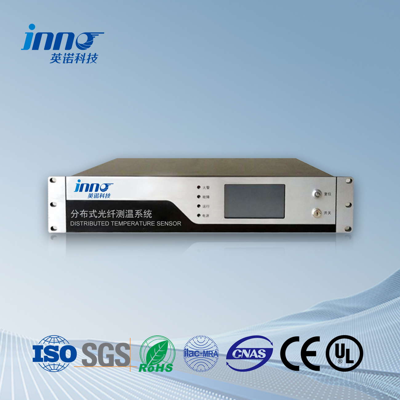
The distributed fiber optic temperature measurement system measures the intensity ratio of anti Stokes light and Stokes light through the Raman scattering effect of laser pulses in the fiber optic cable, thereby determining the temperature at each point of the cable.
1、 The principle of distributed fiber optic cable temperature measurement
Distributed fiber optic cable temperature measurement is based on spontaneous Raman scattering effect and optical time domain reflectometry (OTDR) technologia.
Raman scattering effect: When a high-power narrow pulse laser LD is incident on a sensing fiber, the interaction between the laser and fiber molecules produces extremely weak backscattered light, which includes three wavelengths: Rayleigh, anti Stokes, and Stokes light. inter eos, anti Stokes light is temperature sensitive and can be used as signal light; Stokes light is insensitive to temperature and can be used as a reference light. The thermal vibration of fiber molecules generates Raman scattering, resulting in the formation of Stokes light and anti Stokes light. The intensity of the anti Stokes light signal is temperature dependent, and the temperature of any point in the optical waveguide can be determined by the ratio of the anti Stokes light signal to the Stokes light signal intensity. Exempli gratia, when the temperature of a cable rises at a certain point, the intensity of anti Stokes light at that point will change accordingly. By comparing and calculating with the intensity of Stokes light, the temperature value can be obtained. This method of measuring temperature using Raman scattering effect has the characteristic of high accuracy and can meet the needs of cable temperature monitoring.
OTDR technology: The determination of position is based on OTDR technology. When light is transmitted in optical fibers, scattering occurs due to the microscopic non-uniformity of refractive index in the fibers. By using high-speed data acquisition to measure the echo time of scattered signals, the position of the fiber corresponding to the scattered signal can be determined. Because the transmission speed of light in optical fibers is fixed, by measuring the time from emission to reception of light pulses, the location where scattering occurs can be accurately calculated, thereby achieving the positioning of temperature measurement points along the optical fiber. Exempli gratia, if a temperature anomaly occurs at a certain location on a 10 kilometer long fiber optic cable, OTDR technology can accurately locate the specific coordinates of that location on the fiber optic cable. This technology enables distributed fiber optic temperature measurement systems to not only measure temperature, sed etiam accurate collocare locum temperaturae anomaliae, which is crucial for cable temperature monitoring because it can detect local hotspots on the cable in a timely manner, making it easier to take corresponding measures.

2、 Method for Distributed Fiber Optic Measurement of Cable Temperature
Fiber optic laying: Uno modo, the fiber optic cable should be laid around or inside the cable. If the cable has a multi-layer structure, such as a conductor layer, insulation layer, buffer layer, waterproof layer, and outer sheath arranged in sequence from the inside out, the impact of the fiber laying position on the accuracy of temperature measurement needs to be considered. Generally speaking, the closer the optical fiber is to a possible heat source (such as a conductor layer), the more sensitive it is to temperature changes. tamen, it is also necessary to avoid damaging the optical fiber by physical factors during cable operation (such as cable bending, stretching, etc.). In some practical applications, such as in cable tunnels, optical fibers can be laid along cable trays or parallel to cables in cable trenches to ensure that the optical fibers can fully contact the temperature field around the cables.
Signal acquisition and processing: High power narrow pulse laser pulses LD are incident on the sensing fiber, generating backscattered light. The anti Stokes and Stokes light pass through the splitter module WF, isolating the Rayleigh scattered light, and are received by the same detector (APD). Obtain temperature information by measuring and calculating the ratio of these two light intensities. This process requires high-precision detection equipment and signal processing algorithms to accurately distinguish and process weak scattered light signals. In terms of data collection, it is necessary to ensure that the frequency and accuracy of data collection meet the requirements of cable temperature monitoring. Exempli gratia, in cable environments with rapid temperature changes, a higher collection frequency is required to capture the dynamic changes in temperature in a timely manner.
Temperature calculation and positioning: Based on the ratio of the received anti Stokes and Stokes light intensities, use a predetermined mathematical model to calculate the temperature value. Simul, the optical time domain reflectometry (OTDR) technology is used to determine the position of the temperature measurement point on the optical fiber, thereby achieving a one-to-one correspondence between temperature and position. When calculating temperature, it is necessary to consider the optical properties of optical fibers, parameters of laser pulses, and environmental factors that affect the measurement results. Exempli gratia, losses in optical fibers, power fluctuations in laser pulses, and other factors can all affect the accuracy of the light intensity ratio, thereby affecting the accuracy of temperature calculations. In terms of positioning, it is necessary to ensure the accuracy of positioning so that the corresponding position can be accurately found when the cable experiences temperature abnormalities.
3、 Instrument and equipment for distributed optical fiber measurement of cable temperature
Distributed fiber optic temperature measurement host:
This is the core equipment of the distributed fiber optic temperature measurement system. It can generate high-power narrow pulse laser pulses and couple them into sensing fibers. Exempli gratia, the DTS8000 measurement host can use high-speed narrow pulse semiconductor laser pulses coupled into sensing fibers. By filtering, detecting, and high-speed data acquisition and analysis of weak backscattering signals in the fiber, it can obtain temperature sensitive anti Stokes signals and temperature insensitive Stokes signals, thereby obtaining accurate temperature information distributed along the fiber in real time.
It has diversified functions such as signal processing, signal analysis, high temperature warning, and data transmission. It is possible to process and analyze the collected optical signals, calculate the temperature value based on pre-set algorithms, and determine whether there are temperature anomalies. Once an abnormal situation is detected, the relay output can quickly drive the external sound and light alarm equipment and other linkage devices to ensure timely and effective handling of the abnormal situation.
Different models of temperature measurement hosts have differences in measurement distance, measurement accuracy, measurement time, number of channels, et alia facies. Exempli gratia, some hosts can measure distances of up to 30KM or even longer, with a measurement accuracy of ± 1 ℃, a measurement time of about 3-15s, et 1-8 measurement channels.
Thermal fiber optic cable:
It is both a carrier for signal transmission and a temperature sensing element. Its characteristics directly affect the accuracy and reliability of temperature measurement. Exempli gratia, temperature sensing optical cables with mining armor, flame retardant, and central bundle tube have good compressive strength (short-term 3000, long-term 1500) and tensile strength, suitable for cable temperature monitoring in special environments such as coal mines.
Different types of optical fibers (such as single-mode and multi-mode) can be used for different measurement scenarios. Single mode fiber is suitable for long-distance and high-precision temperature measurement; Multimode fiber has advantages in some short distance and cost sensitive application scenarios.
The length of the temperature sensing optical cable is determined according to the measurement requirements, and can be as long as several kilometers or even tens of kilometers, enabling continuous temperature monitoring of longer cable lines.
Other supporting equipment:
Spectral module WF: used to isolate Rayleigh scattered light, so that temperature sensitive anti Stokes signal light and temperature insensitive Stokes reference light can be received by the same detector (APD), providing accurate light intensity signals for subsequent temperature calculations.
Detector (APD): responsible for receiving anti Stokes signal light and Stokes reference light processed by the splitting module, converting the optical signal into an electrical signal for subsequent signal processing and temperature calculation.
4、 Practical case of distributed fiber optic cable temperature measurement
Application in Fire Detection of Cable Tunnels:
There are a large number of cable tunnels in places such as power plants and steel plants, which are prone to fires due to cable heating and faults. Distributed fiber optic temperature measurement technology is based on the principles of optical time domain reflectometry (OTDR) and backward Raman scattering of optical fibers, which can accurately, timely, and continuously monitor the temperature inside cable tunnels. Exempli gratia, by laying the detection fiber in a cable tunnel, the fiber optic host emits a laser beam into the detection fiber optic cable and collects real-time Raman scattering light with on-site real-time temperature information scattered back along the fiber optic cable. These light signals are analyzed and processed to obtain temperature distribution information on the entire fiber optic cable. When the temperature exceeds the preset alarm value, the fiber optic host emits a fire alarm sound and light indication, and can output alarm information to the fire alarm controller.
The composition of the distributed fiber optic temperature measurement system includes sensing optical cables laid on site, whose function is to obtain the temperature of the on-site cable tray and the ambient temperature; Each distributed fiber optic temperature measurement host is installed in the monitoring room or cable tray or tunnel according to the principle of proximity (if directly installed on site, outdoor equipment with a protection level of IP66 should be selected), responsible for collecting and calculating the temperature measured by the sensing fiber optic cable in real time; The monitoring server collects temperature data from multiple temperature measurement hosts, stores, displays, manages, analyzes, exports, and prints the data by running temperature monitoring software. It can also use Modbus protocol to connect with the fire alarm controller and directly send alarm signals to the fire alarm controller, achieving linkage.
Application in Communication Power Building:
The distributed fiber optic temperature monitoring system is used for temperature monitoring in the computer room of the communication power building, including temperature monitoring of cabinets, bridge cables, and underground tunnel cables. The system includes a local client, fiber optic temperature measurement host, temperature sensing optical cable, and temperature measurement software. By sensing temperature through temperature sensing optical cables, the fiber optic temperature measurement host collects and processes data, transmits temperature information to local clients and temperature measurement software, realizes real-time temperature monitoring, trend analysis, and remote warning and alarm, ensuring safe and stable communication operation. Exempli gratia, when the temperature of the cable tray in the computer room rises abnormally due to high load, the distributed fiber optic temperature monitoring system can detect the temperature change in a timely manner, analyze it through software to determine whether it has reached the alarm threshold, and if it has, issue an alarm signal to notify relevant personnel for inspection and handling, thereby avoiding communication failures or safety accidents such as fires caused by high cable temperature.
5、 Precautions for distributed fiber optic cable temperature measurement
Regarding fiber optic laying and installation:
The laying path of optical fibers should be planned reasonably to avoid being affected by external mechanical stress. If the optical fiber is excessively bent, stretched, or compressed during the laying process, it may increase fiber loss, affect the transmission of optical signals, and thus reduce the accuracy of temperature measurement. Exempli gratia, when laying optical fibers in cable trenches, attention should be paid to the compression of the fibers by other equipment or debris in the trench to ensure that there is sufficient space for the fibers.
The coupling method between optical fibers and cables is also important. If the coupling is improper, it may not be possible to accurately sense the temperature changes of the cable. When installing optical fibers on cables, appropriate coupling methods should be selected based on the type, structure, and working environment of the cable, such as tying, pasting, or fixing with specialized fixtures, to ensure that the optical fibers are in close contact with the cable and can effectively conduct heat.
For long-distance fiber optic installation, the issue of fiber optic splicing should be considered. Fiber optic splice points may introduce losses and reflections, affecting temperature measurement. ergo, high-quality splicing equipment and processes should be used during fiber optic splicing to ensure minimal loss at the splicing point.
In terms of calibration and maintenance of measurement systems:
Regular calibration of distributed fiber optic temperature measurement systems is key to ensuring measurement accuracy. Due to the potential impact of environmental temperature, humiditas, fiber aging, and other factors on the measurement accuracy of the system, it is necessary to regularly calibrate the system using a standard temperature source. Exempli gratia, the measurement results of the system can be compared and adjusted in a constant temperature environment with a known temperature to ensure that the measurement error is within the allowable range.
Regular maintenance should be carried out on temperature measurement hosts, detectors, and other equipment. Check the operating status of the equipment, clean the surface of the equipment, and prevent dust, water vapor, etc. from entering the interior of the equipment and affecting its performance. For APD detectors, their sensitivity and response speed should be regularly checked to ensure accurate reception and conversion of optical signals.
Regular inspections should also be conducted on temperature sensing optical cables to check for any damage, breakage, or corrosion. If damage is found to the optical cable, it should be repaired or replaced in a timely manner to ensure the continuity and accuracy of temperature measurement.
In terms of the impact of environmental factors:
Changes in environmental temperature and humidity may affect the optical properties of optical fibers and the performance of equipment. Exempli gratia, in high temperature and high humidity environments, the loss of optical fibers may increase, and electronic components inside the equipment may experience performance degradation or failure. ergo, when using a distributed fiber optic temperature measurement system in this environment, corresponding protective measures should be taken, such as sealing, moisture-proof, and heat dissipation treatment of the equipment.
If there is strong electromagnetic interference in the measurement environment, although optical fibers themselves have the characteristic of resisting electromagnetic interference, electronic devices in the system (such as temperature measurement hosts) may be affected. In this case, electromagnetic shielding should be applied to electronic devices to ensure that the system can function properly. Simul, it is also necessary to avoid laying optical fibers near strong electromagnetic radiation sources to avoid interference with the optical signals in the fibers.
Fibra optica temperatus sensorem, Magna ratio intelligentis, Distribuit fibra opticus opticus in Sinis
 |
 |
 |
 INNO fibra temperatus opticus sensoriis ,temperatus magna systemata.
