Why does the excitation system need to monitor temperature?
In response to the characteristics of large temperature measurement errors and poor real-time performance of power components in traditional excitation system power cabinets, the basic principle, installation method, and network topology of fluorescence fiber optic temperature measurement are introduced. The application practice of combining fiber optic temperature measurement technology in the excitation system of secondary hydropower stations shows that using fluorescence fiber optic temperature measurement technology has the characteristics of high temperature measurement accuracy, good real-time performance, jednostavna instalacija, and easy maintenance, and has good monitoring effects and broad application prospects.
With the sustained and stable development of the national economy, social progress has entered the fast lane, posing higher requirements for the stable and sustainable operation of the power system. In the power system, temperature is an important indicator for the normal operation of equipment. Due to the current focus on offline monitoring of equipment through regular use of infrared thermal imagers, temperature guns, and other instruments by on duty personnel, such methods have large measurement errors and can only measure the surface temperature of the equipment. They cannot effectively measure and monitor the temperature of enclosed, high-voltage, and strong electromagnetic contact points. Stoga, it is urgent to find a more effective temperature measurement method to achieve more effective temperature monitoring of the equipment.

How can a hydroelectric power station use a fluorescent fiber optic temperature measurement system to monitor temperature?
The second level hydropower station adopts the largest bulb through flow turbine unit in China, equipped with 6 single unit capacity 58MW bulb through flow turbine generator units, with a total installed capacity of 348MW. The rated stator voltage is 10.5kV, which is boosted to 500kV through the main transformer and connected to the 500kV substation.
The secondary hydropower station adopts an excitation system, and the power cabinet adopts a three-phase bridge type fully controlled rectifier circuit, with a rated excitation current of 1015A. The excitation system, as a part of the hydroelectric power generation system, controls the terminal voltage and excitation current of the generator and plays a crucial role in the safe and stable operation of the unit. The controllable silicon and other power components of the excitation system power cabinet are the main heating components of the excitation system, and temperature measurement and real-time monitoring are important indicators for the safe operation of equipment.
The excitation system of the secondary hydropower station adopts fluorescence fiber optic temperature measurement technology to achieve online temperature measurement and real-time transmission of the controllable silicon components in the power cabinet, ensuring the reliable, safe, and stable operation of the excitation system. Practice has shown that fiber optic temperature measurement technology has the characteristics of high measurement accuracy, good real-time performance, jednostavna instalacija, and easy maintenance, and has good monitoring effects and broad application prospects.
What are the basic principles and installation and usage methods of fluorescent fiber optic online temperature measurement devices?
The basic principle and temperature measurement device of fiber optic temperature measurement are fluorescence fiber optic temperature measurement devices, which are more suitable for complex environmental temperature measurement needs such as high voltage and strong electromagnetic, as well as multi-point temperature monitoring with complex topological structures.
What is the principle of fluorescence fiber optic temperature measurement?
The fluorescence fiber temperature sensor used in the fluorescence fiber optic temperature measurement device belongs to the transmission type fiber optic temperature sensor. The sensor probe is composed of multimode fiber optic and fluorescent body, which uses fiber optic as the sensor for transmitting measurement signals. Fluorescents generally use special rare earth fluorescent materials. When the fluorescent material is triggered by a certain wavelength of light, the fluorescence emitted by the fluorescent material decays exponentially. Due to the different decay times of fluorescence at different temperatures, fluorescent fiber optic temperature sensors can be placed in a certain way within the measured temperature range to achieve temperature measurement by measuring the decay life of fluorescence. Contact us for the schematic diagram of fluorescence fiber optic measurement.
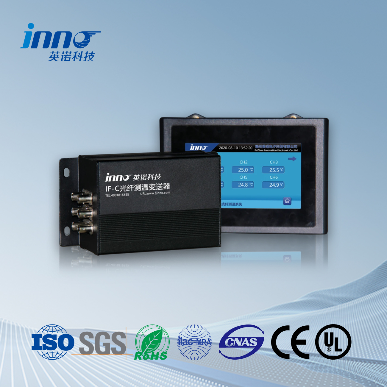
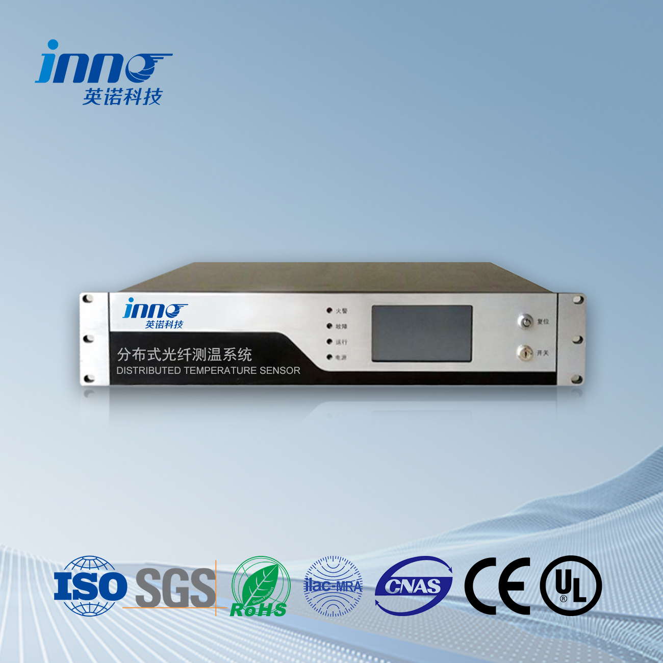
The fluorescence fiber optic temperature measurement device mainly consists of a fluorescence fiber optic sensor, an extended fiber optic, and a fiber optic temperature demodulator. The optical fiber temperature demodulator sends out an excitation light pulse. The light pulse arrives at the fluorescent sensor probe by extending the optical fiber and excites the fluorescence. The fluorescence is returned to the modulator through the temperature resistant optical fiber. The modulator calculates the fluorescence decay life to obtain the corresponding temperature.
Fiber optic temperature demodulators generally have modbus 485 communication function, which uploads the measured temperature signal to the upper computer monitoring system through communication. The upper computer can perform corresponding control or alarm operations based on the measured temperature information.
How is the fluorescent fiber optic temperature measurement device actually applied in hydropower stations?
The excitation system of the secondary hydropower station adopts fluorescence fiber optic temperature measurement technology. The fiber optic temperature probe is directly installed near the position of the thyristor electrode plate, ensuring that the temperature probe can accurately and directly reflect the temperature of the thyristor body, with accurate measurement values and fast response speed. U isto vrijeme, due to the strong insulation performance of temperature resistant optical fibers and extended optical fibers, the insulation performance of the fluorescent fiber temperature measurement device is ensured during the operation of high voltage and high current controllable silicon rectifier bridges, ensuring the safe and stable operation of the device. To ensure the reliable operation of the equipment and accurate temperature monitoring, the excitation system of the secondary hydropower station also uses platinum resistance temperature measurement in addition to fluorescent fiber temperature measurement. Platinum resistance measures the ambient temperature inside the screen cabinet between the installation of controllable silicon, while platinum resistance measures the ambient temperature. Fluorescent fiber directly measures the temperature of controllable silicon, so the temperature measured by platinum resistance is lower than that measured by optical fiber.
At present, the platinum resistance and fluorescent fiber optic temperature measurement devices of the excitation system of the second level hydropower station are operating normally. The platinum resistance temperature measurement temperature of the excitation system of six units is generally about 6 ℃ lower than that of the fluorescent fiber optic temperature measurement, which reflects the actual working condition of the thyristor temperature normally.
What are the specific steps for the installation and use of a fluorescent fiber optic temperature measurement device?
The installation method of the fluorescent fiber optic temperature probe is to open a small hole through the thyristor heat sink. The fluorescent temperature probe coated with rare earth substances is installed in this small hole and comes into contact with the thyristor shell. The small hole is then filled with silicone to fix the fluorescent temperature probe.
The temperature measuring probe is fixed on the thyristor body to truly detect the temperature of the thyristor. Each power cabinet has 6 thyristor components, sa 1 fluorescent temperature measurement point set on each thyristor component. Postoji ukupno 6 temperature measurement points, corresponding to a set of 6-channel fluorescent fiber temperature thermometers.
The excitation system of the second level hydropower station has 6 temperature displays of the controllable silicon. The platinum resistance test temperature in the air duct is 20.31 °C, and the temperature measurement of the 6 fluorescent optical fibers is between 25-27 °C. The temperature displays of the other operating units under the same excitation current are all between 25-27 °C, which truly reflects the current operating temperature of the controllable silicon.
The topology diagram of the fluorescence fiber optic temperature measurement system was obtained from us. The entire power plant temperature measurement system consists of six excitation system temperature measurement devices, various monitoring hosts, data concentration units, centralized monitoring computers, and human-machine interaction software. The centralized data unit and centralized monitoring computer are generally installed in the main control room to facilitate online temperature detection of electrical equipment by operators.
The fluorescent fiber optic online monitoring software system installed in the monitoring computer provides a simple, practical, and efficient monitoring platform. The main functions of the software system include local monitoring of real-time temperature, remote monitoring of real-time data, high/low temperature alarms, high/low temperature warnings, historical data playback, pre – and post alarm curves, and temperature export to Excel. The software system provides a good human-machine interface, powerful data processing capabilities, and can store and query historical data.
What are the characteristics of fluorescence fiber optic temperature measurement?
Fluorescent fiber optic temperature measurement devices use optical fibers as sensors for transmitting measurement signals, which have many advantages such as anti electromagnetic interference, high-voltage insulation, stability and reliability, high accuracy, visoka osjetljivost, small size, long service life, otpornost na koroziju, and good adaptability. They are especially suitable for temperature monitoring in special industrial environments such as high voltage and strong electromagnetic interference (electromagnetic interference EMI, radio frequency interference RFI, and electromagnetic pulse EMP). The application of fluorescent fiber optic online temperature measurement device in the excitation system of secondary hydropower stations effectively solves the real-time temperature monitoring function of controllable silicon components, and the measured values accurately reflect the true values of the equipment, achieving good measurement and monitoring effects. U isto vrijeme, this temperature measurement device can also be widely promoted for online temperature monitoring of high current equipment joints such as stator welding blocks, visokonaponski rasklopni uređaji, generator outlet busbar joints, cable terminals, itd., providing better protection for the safe and reliable operation of the power system.
Senzor temperature od optičkih vlakana, Inteligentni sustav nadzora, Distribuirani proizvođač optičkih vlakana u Kini
 |
 |
 |
 INNO senzori temperature od optičkih vlakana ,Sustavi za nadzor temperature.
