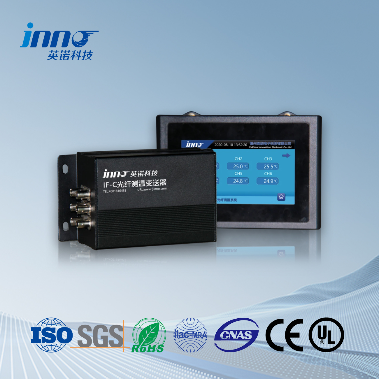
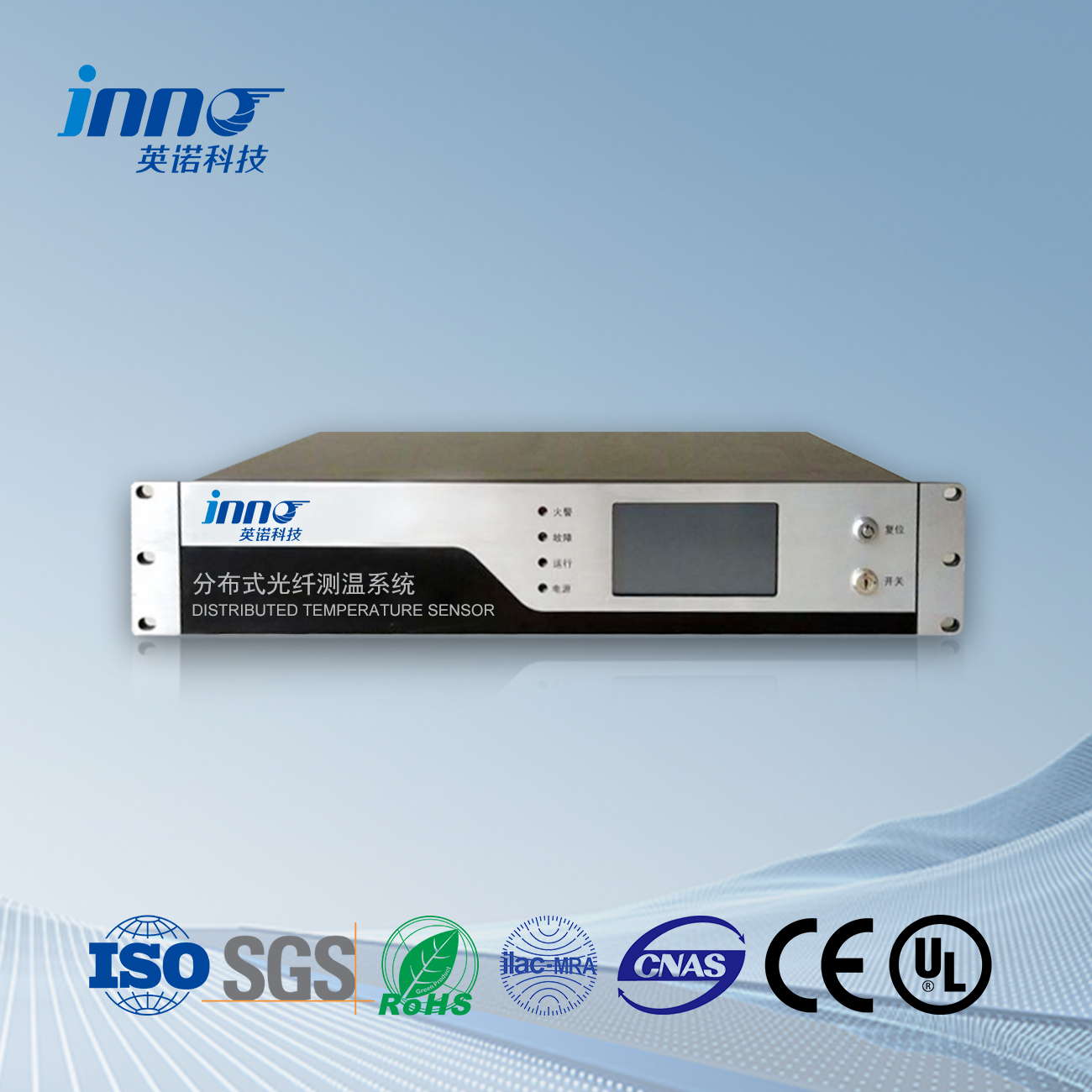
With the economic development of cities, the application of 10kV cable lines in urban distribution networks is becoming increasingly widespread, and ring main cabinets and switching stations are also widely used in distribution network cable lines. As a weak link in the safe and reliable operation of the power grid, the performance and quality of cable heads not only depend on the material of the cable head, but also on the manufacturing process of the cable head, and are related to the real-time load size. Any of the above factors may cause heating of the cable heads inside the 10kV ring main unit, switching station, and switchgear. If not inspected or monitored in a timely manner, the load will continue to increase, and the temperature of the cable head will rise until it causes an explosion of the cable head. It may even cause the insulation sleeve inside the cabinet to burst, and the SF6 common gas box to leak, resulting in the entire ring main unit or switchgear being scrapped. A common two in four out ring main unit is worth 300000 yuan, plus maintenance material costs, construction costs, and power outage losses, resulting in losses of several hundred thousand yuan. The cost of switching stations is higher, and the losses will be greater, so the consequences are quite serious. It is necessary to strengthen inspections and temperature measurements to prevent accidents from happening.
Fluorescent fiber optic temperature measurement system for switchgear switching stations and cable joints
(1) Realize early prediction of equipment failures caused by overheating, and take preventive measures;
(2) When an overheating fault occurs, the system can provide an alarm and accurately locate the overheating position, guiding maintenance work.
(3) Visually display the specific locations and names of cable joints, equipment, and bus temperatures, and continuously monitor temperature in real-time. Save historical data as a basis for accumulating operational experience and analyzing accidents.
(4) Equipped with RS485 network interface, it can be connected to the management network within the station to achieve information sharing. Computers connected to the local area network within the station can also have temperature display and alarm functions. The host installed in the main control room and connected computers can automatically display corresponding alarm prompts.
(5) The fiber optic temperature online monitoring and control system, as a substitute for traditional temperature sensing fire detectors, has advantages such as high accuracy, fast data transmission and reading speed, good adaptive performance, and accurate and intuitive fault detection. It realizes many functions that traditional temperature measurement cannot achieve and problems that cannot be solved on site.
(6) Different alarm temperatures can be set for each temperature sensor through the system as needed. When the temperature reaches the predetermined value, the system alarms and displays the position of the faulty cable head.
(7) The system can analyze and judge whether the temperature of the switchgear and cable heads is normal or not, and alarm potential accidents based on the trend of temperature changes. It has functions such as over temperature alarm, abnormal temperature rise alarm, automatic recording and printing of out of limit accidents, and accident recall.
Advantages of fiber optic temperature measurement system for switchgear
1. Stable operation. U Sustav za mjerenje temperature optičkih vlakana has the function of online collection, monitoring, and analysis of on-site temperature. These analyses include over temperature analysis, temperature rise trend analysis, temperature gradient analysis, and automatic environmental temperature compensation. It can also make alarms, comparisons, historical records, and other processing to ensure that handling is done before cable accidents occur. These methods are all based on extensive on-site practice and have high reliability and accuracy.
2. Visual display
U temperature measurement system of the switchgear fully utilizes the advantages of temperature monitoring, displaying the temperature value diagram of the switchgear intuitively on the software interface, and displaying the distribution positions of the switchgear contacts and cable joints in the switchgear layout diagram, which can display the temperature value of the measured point in real time and intuitively. The historical record analysis function predicts fire accidents in switchgear and cable joints, and saves the temperature changes at all measurement points since the system installation. By selecting different measuring points and time periods as needed, the operation of the switchgear and cable joints can be comprehensively analyzed. Based on the trend of temperature rise, the aging degree of switchgear and cable joints can be predicted early, and the possible locations of overheating faults can be determined, providing a basis for equipment maintenance.
3. Flexible parameter settings
U Mjerenje temperature optičkih vlakana device for switchgear meets various complex on-site requirements. Flexible parameter settings make the system’s analysis and alarm functions more comprehensive. Users can flexibly configure parameters such as recording intervals, recording methods, temperature alarm values, and temperature trend alarm values based on the actual situation on site.
4. The comprehensive online device self inspection function effectively ensures the safe operation of the equipment. The system has device self inspection function and self diagnosis ability, which facilitates equipment inspection and maintenance work, while also ensuring the normal and effective operation of the equipment.
U Fluorescentni sustav za mjerenje temperature optičkih vlakana is very suitable for online monitoring of high-voltage switchgear and cable heads. Currently, it is mostly used in 35/10kV power supply systems across the country. Each fluorescent fiber optic terminal is connected to a fiber optic temperature sensor corresponding to a temperature measurement point, which is easy to install and implement and easy to expand. Practice has proven reliable operation, timely detection of hidden dangers, achieving predictive control of equipment, effectively reducing power supply accidents, and providing a basis for planned maintenance. It is worth promoting and applying on other equipment that requires online temperature measurement.
Senzor temperature od optičkih vlakana, Inteligentni sustav nadzora, Distribuirani proizvođač optičkih vlakana u Kini
 |
 |
 |
 INNO senzori temperature od optičkih vlakana ,Sustavi za nadzor temperature.
