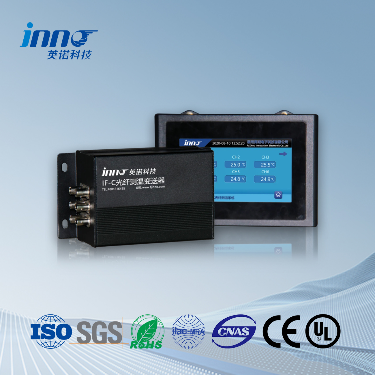
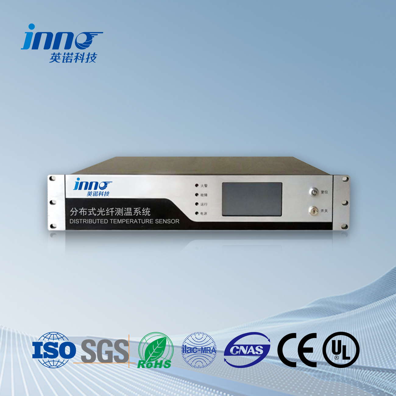
Kyn28 switchgear contact temperature measurement. The best alternative to 6-point wireless temperature measurement in switchgear is the temperature measurement fiber optic system. Online temperature measurement in switchgear is a device for measuring the nine and six points of high-voltage cabinets. How to measure fiber optic temperature, how to install fiber optic temperature measurement cables, and what is the principle of temperature measurement fiber optic. Fiber optic temperature measurement manufacturers provide detailed solutions and prices. Please feel free to contact FJINNO.
The problem of high current overheating has been troubling the power system and large capacity new users. Personal injury and property damage caused by overheating of electrical products or materials are very serious every year, and some malignant group injury and death accidents are related to high current overheating. Stoga, real-time monitoring of high current overheated parts of high-voltage electrical products is very important.
High voltage switchgear is an important equipment in power transmission and distribution systems, which plays an important role in breaking and closing power lines, and has been increasingly widely used in power systems. With the implementation of the 11th Five Year Plan and the development of the national economy, society has put forward higher requirements for power supply reliability. Large scale transmission and distribution, as well as grid security, have been identified as priority themes in the energy sector. The safety and reliability of power equipment is an important link in ensuring the safety of large-scale transmission and distribution as well as the power grid. As a widely used power equipment, high-voltage switchgear has received more attention for its safety and reliability. According to incomplete statistics, many domestic power generation and power companies have experienced varying degrees of high-voltage switchgear failures, causing certain economic losses. Some of these faults are due to quality issues with the switchgear itself, and the more important reason is the lack of effective monitoring methods for the switchgear at present. At present, the monitoring of high-voltage switchgear is mostly based on manual inspection, using handheld infrared thermometers to obtain temperature data inside the switchgear. Due to the relatively complex structure of the switchgear and the influence of component occlusion, infrared thermometers often cannot obtain accurate temperature data, and the inspection interval is long. The maintenance of power equipment in the power system is transitioning from fault diagnosis and preventive maintenance to condition based maintenance. As a widely used high-voltage switchgear in transmission and distribution systems, it is necessary to implement condition based maintenance on it. Stoga, the research and development of a new high-precision and highly reliable online temperature monitoring and fault diagnosis system for high-voltage switchgear is of great significance.
FJINNO comprehensively considers the real-time internal temperature and load factors of high-voltage switchgear, and has developed a fiber optic online thermometer for high-voltage switchgear, which is used for real-time online detection of the temperature of high-voltage live nodes. This instrument integrates photoelectric sensing technology, electronic processing technology, and high-voltage electromagnetic field processing technology, solving the problem of online real-time temperature measurement of high-voltage charged nodes. It plays a positive role in improving the quality of power supply and the reliability of power supply equipment, ensuring the safety of power supply equipment, and eliminating hidden dangers in safety production.
A new high-precision, highly reliable, and cost-effective fiber optic temperature online monitoring and fault diagnosis system for high-voltage switchgear. In the design, inappropriate infrared or wireless temperature sensors were not used, and advanced technology temperature sensors integrated with fluorescent fiber optic were adopted. The sensor cabinet was arranged reasonably, and the distribution of temperature field inside the cabinet was obtained from the data measured by the sensors. Based on this, the status of the high switch cabinet was diagnosed, the temperature development trend was predicted, and possible faults were warned.
Fiber optic can be used for online real-time temperature detection at contacts, Glave kabela, bus joints, and other locations inside high-voltage switchgear. According to user requirements, it can be measured individually and in a single cabinet, or combined with a comprehensive automation system to form an independent temperature monitoring system, which can monitor and measure all nodes, busbars, cable joints, itd. of the operating equipment in the substation in real time. The temperature signal can be remotely transmitted by computers, enabling remote monitoring of all heating nodes in the entire switchgear, and solving the problem of increasing unmeasurable temperature parameters of unmanned distribution room operating equipment.
Functional characteristics of fiber optic temperature measurement system for switchgear
1. 3/6/9/12 channel fiber optic temperature measurement, a standard universal regulator temperature, particularly suitable for industrial environments such as high-voltage transformers, high-voltage frequency converters, and switchgear;
2. Real time display of the temperature of the measured point, the set alarm and trip temperatures can be changed through panel buttons, and the corresponding channel names can be modified;
3. Output switch signals, including over temperature alarm, over temperature trip, and instrument temperature measurement fault signals;
4. Output a 4-20mA analog signal to instantly transmit real-time highest point temperature data to the monitoring interface of the user control system;
5. Can control the cooling fan to achieve manual and automatic start/stop of the fan, as well as set the fan start/stop target value and return difference function (optional);
6. Network output is achieved through methods such as RS-485 and CAN bus, and standard configuration calculations are utilized.
Senzor temperature od optičkih vlakana, Inteligentni sustav nadzora, Distribuirani proizvođač optičkih vlakana u Kini
 |
 |
 |
 INNO senzori temperature od optičkih vlakana ,Sustavi za nadzor temperature.
