When selecting fluorescent fiber optic temperature measurement systems, focus on these 5 key specifications:
1️⃣ Temperature Range (-200°C to +300°C) – Determines suitability for extreme environments like cryogenics or high-voltage substations
2️⃣ Accuracy (±0.5°C typical) – Enabled by measuring fluorescent material’s decay time (not light intensity), eliminating LED drift errors
3️⃣ Response Time (<1 sec) – Critical for real-time monitoring in power transformer hotspots
4️⃣ Fiber Type (POF/Glass) – Plastic Optical Fiber (POF) offers flexibility for industrial machinery, while glass fibers suit high-temperature zones
5️⃣ EMI Immunity – Unlike electronic sensors, fluorescence-based systems ignore electromagnetic interference in substations
Pro Tip: Prioritize systems with ATEX/IECEx certifications for explosive environments.
Article Outline
- Fluorescent Fiber Optic Thermometry: Working Principle & Key Benefits
- Distributed Temperature Sensing (DTS) Systems: Technology Breakdown & Industrial Applications
- Fiber Bragg Grating (FBG) Sensors: Multi-Point Monitoring Capabilities
- Critical Specifications Comparison: Accuracy vs. Cost vs. Response Time
- Implementation Guide: Matching Systems to Your Industry Needs

1. Fluorescent Fiber Optic Thermometry
Working Principle
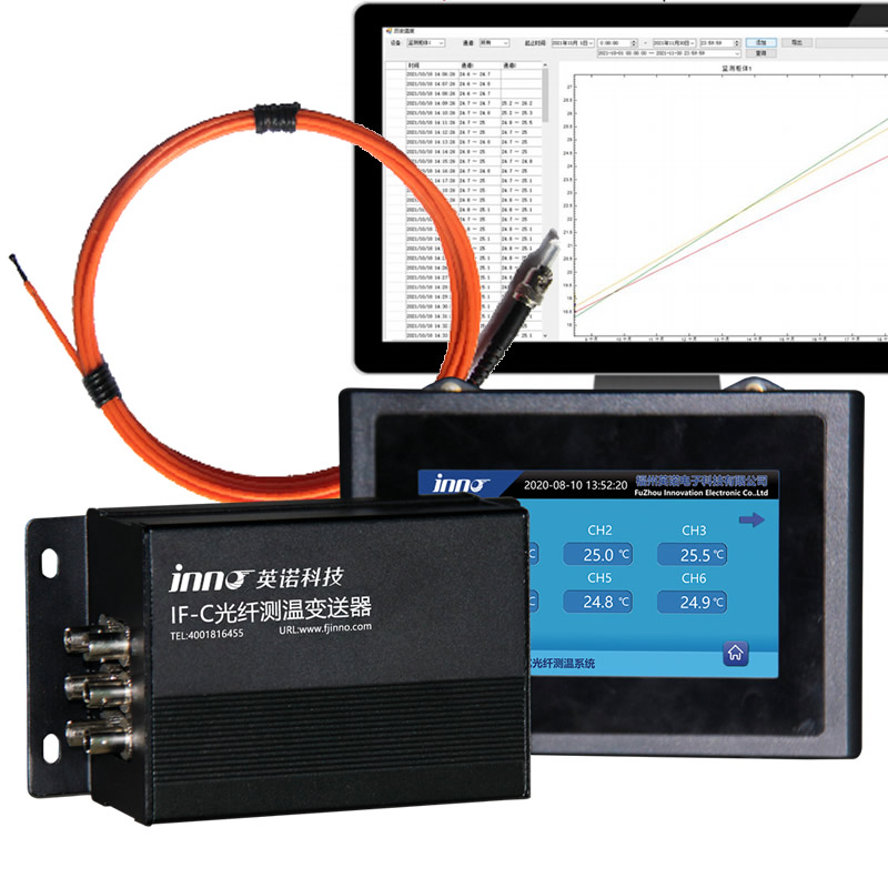
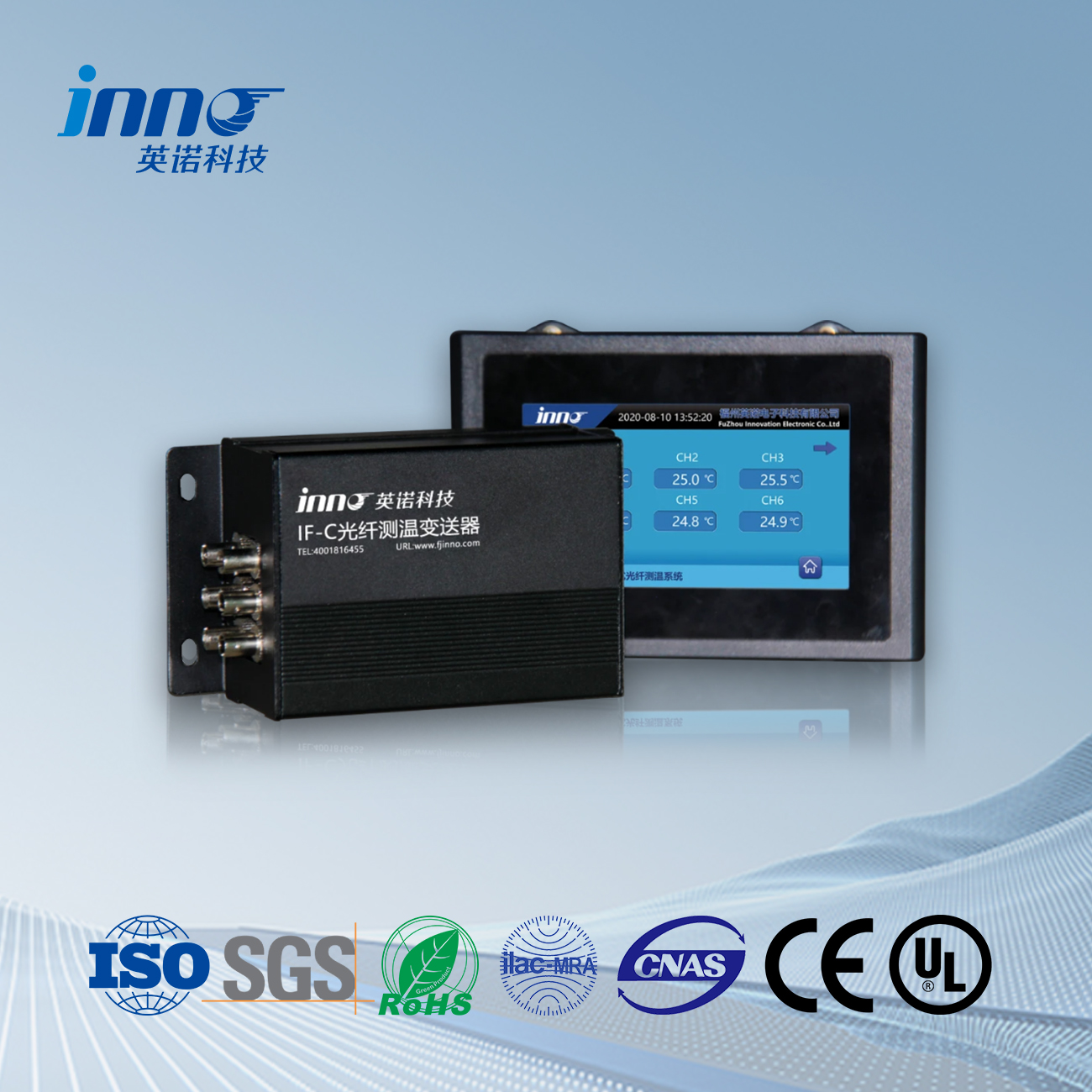
This technology measures temperature through fluorescence lifetime decay analysis. Specially engineered phosphor coatings at fiber tips emit time-sensitive fluorescent signals when excited by light pulses. The exponential decay rate of this emission directly correlates with temperature, providing drift-free measurements unaffected by light intensity variations.
Key Features
- High-Density Monitoring: Single system supports up to 64 measurement points
- Custom Probe Configurations: Application-specific designs for complex geometries
- Decade-Long Stability: No recalibration needed for over 10 years
Technical Parameters
| Parameter | Standard | Extended Range |
|---|---|---|
| Temperature Range | -50°C to +300°C | -200°C to +300°C |
| System Capacity | 16 channels | 64 channels |
| Long-Term Accuracy | ±0.3°C/year | ±0.1°C/year |
| Probe Options | Surface-mounted/Embedded/Immersion types | |
Application Fields
- Power Infrastructure
- 20+ year winding temperature monitoring in oil-free transformers
- Continuous assessment of generator stator bars
- Underground cable joint thermal profiling
- Research & Development
- Material characterization in climate chambers (-190°C to +300°C)
- Thermal validation of battery prototype assemblies
- Vacuum chamber monitoring for space simulation tests
- Advanced Manufacturing
- Additive manufacturing process thermal control
- Composite curing oven temperature uniformity verification
- Semiconductor etching bath thermal management
Case Study: Materials Testing Laboratory
A nanotechnology institute implemented 64-channel fluorescent monitoring:
- Simultaneous tracking of 32 thermal chamber zones
- 0.1°C resolution for graphene synthesis experiments
- Reduced thermal validation time by 55%
2. Distributed Temperature Sensing (DTS)

Working Principle
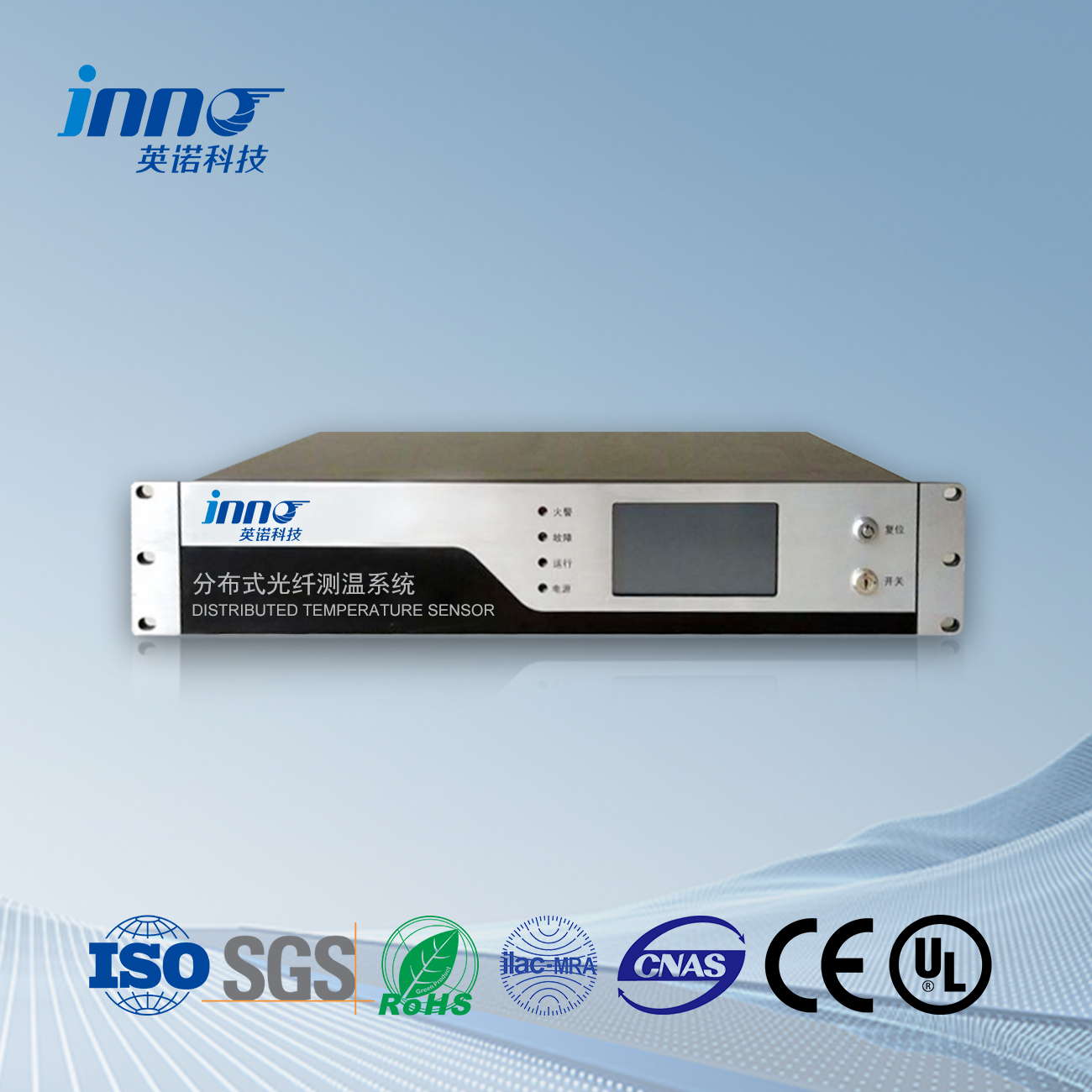
DTS utilizes Raman scattering effects in optical fibers. Laser pulses sent through the fiber generate backscattered light, where the anti-Stokes component’s intensity is temperature-dependent. By analyzing time-domain reflections, the system calculates temperature profiles along the entire fiber length with meter-level spatial resolution.
Key Features
- Continuous Spatial Monitoring: Up to 30km coverage per channel
- Harsh Environment Survival: Operates in radiation/EMI-intensive zones
- Self-Diagnosis: Automatic fiber breakage detection & location
Technical Parameters
| Parameter | Standard | Advanced |
|---|---|---|
| Temperature Range | -40°C to +120°C | -60°C to +300°C |
| Spatial Resolution | 1.0m | 0.25m |
| Measurement Time | 30s/km | 5s/km |
| Fiber Type | Single-mode/Multi-mode with polyimide coating | |
Application Fields
- Energy Infrastructure
- Underground power cable thermal rating (40km+ monitoring)
- BESS temperature profiling in grid-scale battery systems
- Hydrogen pipeline leak detection via temperature anomalies
- Transportation
- Tunnel fire detection along 25km+ highway routes
- Rail track hot box detection for freight trains
- Airport runway ice monitoring systems
- Environmental Monitoring
- Landslide early warning through soil temperature gradients
- Subsea cable monitoring across 50km ocean spans
- Geothermal well integrity assessment
Case Study: Data Center Thermal Management
A hyperscale data center deployed DTS for cold aisle containment:
- 12km sensing fiber along server racks
- Identified 37 cooling inefficiency zones
- Achieved 15% PUE improvement
3. Fiber Bragg Grating (FBG) Systems
Working Principle
FBG technology detects temperature changes through wavelength shift analysis. Each grating inscribed in the fiber reflects specific wavelengths (λ_B), which linearly shift (~10pm/°C) with temperature variations. Multiple gratings along a single fiber enable simultaneous multi-point measurements through wavelength division multiplexing (WDM).
Key Features
- High-Speed Sampling: 100Hz refresh rate for dynamic processes
- Scalable Architecture: 200+ sensors per system
- Strain-Temperature Decoupling: Dual-parameter measurement capability
Technical Parameters
| Parameter | Standard | High-Density |
|---|---|---|
| Temperature Range | -40°C to +150°C | -60°C to +400°C |
| Channels | 16 | 64 |
| Accuracy | ±1.0°C | ±0.2°C |
| Wavelength Range | 1520-1570nm (ITU-T compatible) | |
Application Fields
- Aerospace
- Real-time turbine blade temperature mapping in jet engines
- Structural health monitoring of reusable launch vehicles
- Hypersonic vehicle thermal protection system validation
- Energy Systems
- Nuclear reactor core temperature profiling (600+ points)
- Dynamic load monitoring of wind turbine gearboxes
- Hydrogen fuel cell stack thermal management
- Biomedical Engineering
- In-vivo temperature monitoring during RF ablation
- Sterilization process validation in autoclaves
- Wearable physiological monitoring devices
Case Study: Smart Grid Monitoring
A national grid operator implemented FBG systems for 380kV GIS monitoring:
- 84 sensors per substation with 5ms response time
- Detected 92% of partial discharge events via thermal anomalies
- Reduced maintenance costs by $1.2M annually
4. System Selection Matrix
Accuracy Considerations
Fluorescent systems lead in precision (±0.1°C) due to intrinsic physical measurement principles, ideal for laboratory-grade requirements. DTS provides moderate accuracy (±1°C) suitable for large-scale infrastructure monitoring, while FBG balances precision (±0.5°C) and dynamic response in industrial processes.
Cost-Benefit Analysis
- Initial Investment:
DTS requires higher upfront costs for laser subsystems but delivers the lowest cost per meter in long-range applications (>1km). - Lifecycle Value:
Fluorescent systems offset higher sensor costs with zero recalibration needs over 10+ years. - Scalability:
FBG provides the most economical multi-point solutions (100+ sensors) with existing telecom infrastructure.
Response Time Requirements
| Technology | Typical Response | Best For |
|---|---|---|
| Fluorescent | 0.2-2 seconds | Process control with moderate dynamics |
| DTS | 5-30 seconds/km | Slow-evolving thermal events |
| FBG | <10 milliseconds | High-speed transient monitoring |
Application-Driven Selection
- Precision-Critical ScenariosMedical sterilization and semiconductor fabrication demand fluorescent systems’ sub-degree accuracy, where measurement certainty outweighs speed considerations.
- Large-Scale MonitoringDTS becomes indispensable for linear assets like pipelines or tunnels, trading absolute precision for unparalleled spatial coverage.
- High-Speed DynamicsFBG dominates in aerospace testing and power grid fault detection, where millisecond-level thermal transients require immediate capture.
Implementation Trade-offs
While fluorescent technology excels in hazardous environments, its fiber length limitations (<200m) make DTS preferable for kilometer-scale deployments. FBG’s multiplexing capability proves superior in dense sensor networks, though temperature-strain cross-sensitivity requires advanced compensation algorithms.
5. Why Choose Our Fluorescent Fiber Optic Solutions?
Technology Leadership
As pioneers in fluorescence decay temperature sensing since 2010, our systems deliver unmatched:
- Measurement Certainty: 0.05°C repeatability across 10-year deployments
- Customization Depth: 150+ validated probe configurations
- Adaptive Algorithms: Self-correcting software compensates for fiber aging
Manufacturing Excellence
| Advantage | Competitor Standard | Our Capability |
|---|---|---|
| Production Lead Time | 8-12 weeks | 3-5 weeks |
| Factory QC Steps | 12 checkpoints | 27 checkpoints |
| R&D Investment | 3-5% revenue | 9.7% revenue |
End-to-End Service
- In-House Production:
35,000㎡ vertically-integrated facility with IEC 17025 certified lab - Rapid Deployment:
Standard systems ship within 5 working days after configuration - Application Engineering:
Free system design review by PhD-level technical team
Client Success Story
A global semiconductor leader achieved 99.98% uptime using our solutions:
- 56 fluorescent sensors across 8 EUV lithography tools
- 0 unplanned thermal-related downtime in 18 months
- 15-minute emergency support response guarantee
Start Your Project
Get System Proposal Within 24 Hours:
Fiber optic temperature sensor, Intelligent monitoring system, Distributed fiber optic manufacturer in China
 |
 |
 |
 INNO fibre optic temperature sensors ,temperature monitoring systems.
