 INNO fibre optic temperature sensors ,temperature monitoring systems.
Why does the traction power supply system of rail transit need to use fluorescent fiber optic temperature measurement
The power supply systems for traction power supply in urban rail transit in China are DC750V and DC1500V, corresponding to the current collection methods of the third rail and overhead contact network, respectively. The maximum voltage of the secondary winding of this power supply system’s transformer has exceeded 1000V, but the measurement range specified in the “Electronic Temperature Controller for Transformers” (JB/T7631-2016), which uses Pt100 as the temperature sensor, can only be limited to below 1000V. Therefore, rail transit has higher voltage resistance requirements for temperature sensor probes and leads.
The fiber optic temperature controller for rail transit uses fluorescent fiber optic temperature sensors as temperature sensing elements. This temperature sensing element is immune to electromagnetic interference and resistant to high voltage (100KV/fiber to ground lead distance of 0.4m). Fluorescent fiber optic temperature measurement completely cuts off the interference of temperature measurement elements transmitted to the temperature controller from the temperature measurement source, improving the safety level of rail transit.
Advantages of Fluorescent Fiber Optic Temperature Measurement System Applied in Rail Transit
For the operating environment of rail transit transformers, isolation and shielding from external electrical interference signals are achieved from the power supply, signal input end, signal output end, and temperature control box shell.
The power supply system of rail transit traction power supply is based on DC750V and DC1500V, while the measurement range specified in the “Electronic Temperature Controller for Transformers” (JB/T7631-2005), which uses Pt100 as the temperature sensor, can only be limited to below 1000V. Therefore, the fiber optic temperature controller has extremely strong voltage resistance and can withstand 100KV.
In response to vibration, dust, humidity, oil pollution and other on-site working environments, multi-layer protective measures are taken to ensure that the optical fiber temperature controller for rail transit has good electromagnetic compatibility, ensuring the stable and reliable operation of the temperature controller.
Design principles of fluorescence fiber optic temperature measurement system
Principle of practicality
The system construction adheres to the principle of practicality. On the basis of practicality, progressiveness and foresight are considered, and standard, advanced and mature products and development platforms are selected to build a system that is practical and solves practical problems.
Standardization principle
The system software and hardware platforms and application development tools used in application construction should comply with national standards, standards of the Ministry of Information Industry, relevant technical specifications and requirements of the company.
The principle of uniformity
Following the policy of centralized information management, overall planning, overall design, and step-by-step implementation, the implementation process embodies four unified principles: unified leadership, unified planning, unified standards, and unified organization and implementation.
Reliability principle
The software and hardware resources need to ensure the uninterrupted and reliable operation of the fiber optic temperature measurement system for 7 × 24 hours. Therefore, it is necessary to equip a complete design of reliability measures to ensure the highly reliable operation of the system and fully consider the reliability requirements of key system applications.
Reliable security mechanism
This system adopts a series of secure encryption measures, with a built-in 64 bit encryption algorithm. The system has higher security and can effectively prevent data leakage and theft, ensuring the security, accuracy, and integrity of the system’s data, and preventing illegal operator operations and legitimate operator illegal operations.
The operation interface is simple, friendly, and highly intelligent
The system automatically checks the legality of the input data and provides friendly prompts for operator errors.
Stable operation and reliable data.
The platform is easy to operate, easy to master, and the installation process is simple. Data can be automatically generated into various reports as needed, improving management efficiency.
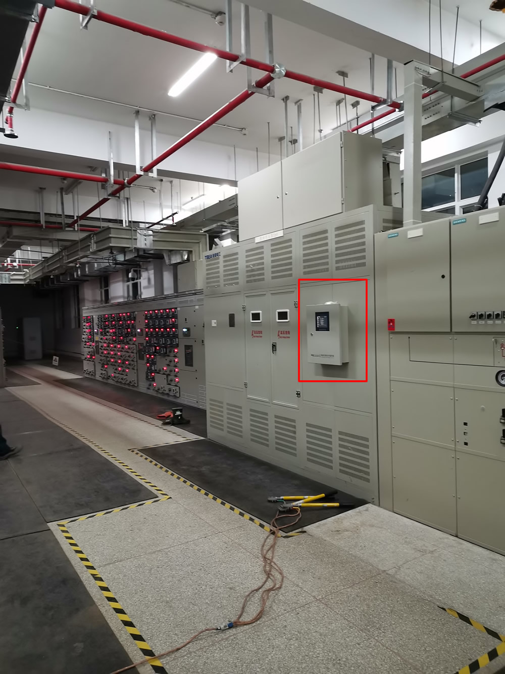
Introduction to wiring and installation of fiber optic temperature controllers for rail transit
Structural framework
The system consists of three parts: a fluorescent fiber optic temperature controller, a fluorescent fiber optic probe, and fiber optic communication software.

The data transmission between the backend system and the temperature measurement terminal adopts RS485 communication method.
All data collection, management, and temperature display are completed by communication software, and the system mainly realizes data collection and monitoring of temperature measurement. The fiber optic temperature measurement terminal integrates multi-channel fluorescent optical fibers, providing external RS485 communication, anti-interference, and corrosion-resistant design.
Application functions of optical fiber temperature measurement system in rail transit
Real time monitoring
The data collection density can be set according to customer needs, and the system will collect data regularly based on the set parameters. Then, it will be displayed in table form or curve drawing to achieve real-time monitoring. Real time monitoring of equipment operation status; Real time monitoring and recording of reactor temperature.
Basic functions of optical fiber temperature measurement system for rail transit
1) Temperature data query
1. You can query temperature data for specified dates, browse, print, and export to Excel.
2) Historical temperature data storage
1. Permanently record temperature data
Introduction to Fiber Optic Temperature Controllers for Rail Transit
main features
The fiber optic temperature controller for rail transit is embedded installation. This product has unique technical advantages in temperature measurement in special environments such as high voltage, strong electromagnetic interference, etc. The temperature hotspot and measurement signal receiving part of the fluorescent fiber optic temperature sensor do not use electrical connections, which can work with high precision and stability for a long time, greatly improving its application range. The fiber optic temperature controller has high accuracy and sensitivity, is resistant to high pressure and can be remotely monitored, has a long lifespan, is small in size, makes instrument maintenance simple and convenient, and ensures safe transportation.
Main functions of optical fiber temperature controllers for rail transit
Provide three winding temperature measurement; Automatic/manual start stop cooling fan function; Digital compensation function for display values of each channel
LCD liquid crystal display patrols to display the temperature of transformer hotspots; Provide clock function;
Provide black box function, which can record temperature data and historical maximum temperature before three power outages;
Provide transformer door cabinet point opening alarm function;
Provide 2 pairs of over temperature alarm contacts (one normally open and one normally closed);
Provide 6 pairs of over temperature trip contacts (three normally open and three normally closed);
Provide 2 pairs of iron core alarm contacts (one normally open and one normally closed);
Provide 2 pairs of remote transmission contacts for fans (one normally open and one normally closed);
Provide 2 pairs of temperature controller power-off alarm contacts (one normally open and one normally closed);
Provide 2 pairs of temperature controller fault alarm contacts (one normally open and one normally closed);
Fan fault diagnosis function and provision of fan fault alarm contacts (L function);
One iron core temperature measurement and one iron core over temperature alarm contact (I function);
Provide RS485 communication function, communication with time mark can receive timing or MODBUS-RTU protocol (F function)
Additional functions of optical fiber temperature measurement system for rail transit
Provide 4 independent 4-20mA analog current output functions; (E function)
PTC nonlinear resistance sensing temperature measurement protection function; (C function)
Alarm function for winding temperature rise rate and iron core temperature rise rate;
The communication protocol can adopt methods such as Profibus, IEC60870-5-103, Ethernet communication, etc;
Fiber optic temperature sensor, Intelligent monitoring system, Distributed fiber optic manufacturer in China
 |
 |
 |
