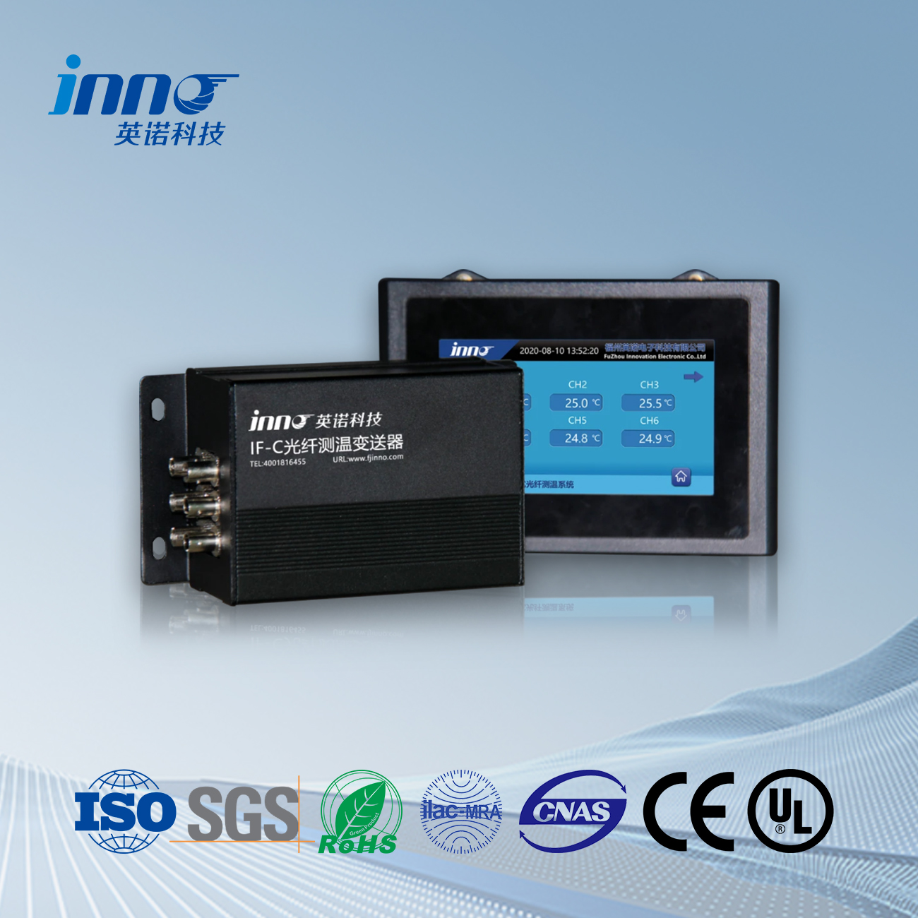
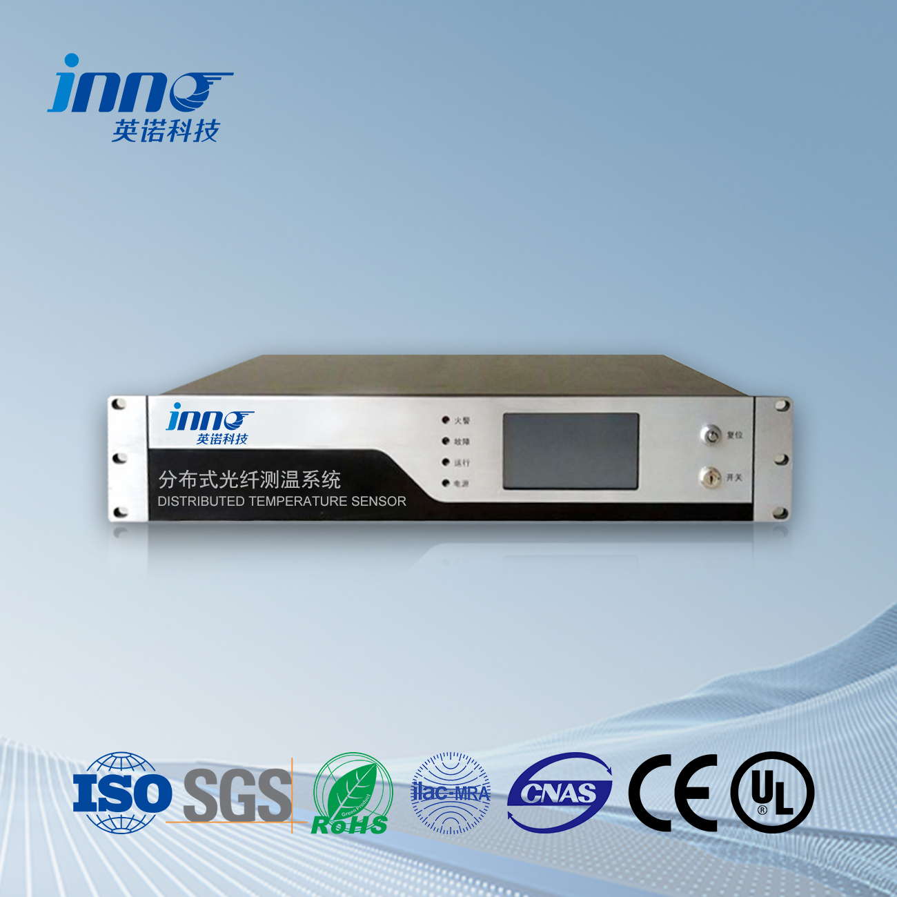
Connect the distributed fiber optic linear temperature fire detector to a 24V reliably grounded DC power supply (to ensure the normal operation of the instrument, the power supply voltage cannot be lower than 85% of the rated voltage and cannot be higher than 110% of the rated voltage). After confirming the correct connection, insert the power switch key and rotate it 90 degrees clockwise to start the power. The front panel power indicator light will also light up. After 15 minutes of system preheating, o distributed fiber optic fire detector entered working mode. Warning: To ensure the personal safety of testing personnel, please confirm that your power supply system is reliably grounded before connecting to the distributed fiber optic linear temperature fire detector.
Running Main Interface: After the system is turned on and running, it enters the running main interface. The running main interface can be divided into fire alarm interface, self check interface, setting interface, and recording interface.
Indicator lights: power indicator light, operation indicator light, fault indicator light, and fire alarm indicator light.
Power indicator light: When the detector is powered on, this indicator light lights up and the color is green;
Operation indicator light: When the detector enters the system and is under normal monitoring, this indicator light will light up and the color will be green;
Fault indicator light: When the detector detects a fault, this indicator light lights up and the color is yellow
Fire alarm indicator light: When the detector detects a fire alarm (differential or constant temperature), this indicator light lights up and the color is red.
Mute button: This button is a mute function button. When the system emits a fire alarm or malfunction sound, press this button to silence it.
Function button: This button is a switch function button between various display interfaces.
Flip up button: This button is the page up button. When in the query record interface, press this key to display the content flipping forward.
Flip down button: This button is the page down button. When querying the record interface, press this key to display the content and scroll back. At the same time, press this key in the self check interface to start the self check. For specific operations, please refer to the basic operations in the next section.
(1) The LCD screen can be divided into fire alarm interface, self check interface, setting interface, and recording interface according to the display interface. Switch between different interfaces using the “Function” button on the panel. When the user presses the “Function” button, the displayed content switches to the corresponding display interface. The name and icon of the function in the interface light up, indicating that it has been switched to the operation of the corresponding function.
(2) Fire alarm interface: Real time display of current fire alarm and fault information. The fire alarm and fault information is displayed in columns, in the format of serial number, time, type, and location. The fire alarm interface also includes the current number of fire alarms and faults, making it easy for users to count the number of fire alarms and faults. At the same time, the temperature setting value is also displayed after the total number of fire alarms. Synchronize display of system time and current detector name at the bottom of the fire alarm function interface
(3) Fire alarm and fault information format: Each fire alarm or fault information is displayed in a row. Each line of fire alarm and fault information is divided into four parts: serial number, time, detector type, location information, and fire alarm type (temperatura diferencial, fixed temperature). Serial number: A serial number numbered in the chronological order of the occurrence of a fire alarm or malfunction, with fire alarm and malfunction information numbered separately. Time: The time when a fire alarm or malfunction occurred, displayed in the form of xxxx year xx month xx day xx hour xx minute xx second.
Detector type: Distributed fiber optic linear thermal fire detector, displaying “linear”.
Location information: indicates the location of a fire alarm or malfunction. Indicate the location information of a fire or malfunction with “XX channel XXXX meters”.
Fire alarm type: indicates the type of fire alarm that occurred, either constant or differential temperature.
(4) System self-test function: Users can switch to the self-test interface by pressing the “Function” button, follow the prompts on the screen, and then press the “Flip Down” button to execute the system self-test program. Self inspection content and sequence: The operation indicator light flashes twice, the fault indicator light flashes twice, the alarm indicator light flashes twice, the buzzer emits a fault sound and a fire alarm sound respectively, the display screen swipes for detection, and the self inspection is completed. The indicator light flashes twice, the alarm indicator light flashes twice, the buzzer emits a fault sound and a fire alarm sound respectively, the display screen swipes for detection, and the self check is completed.
(6) Record interface: Display historical fire alarm and fault information, with a maximum of 999 fire alarm and fault information displayed. The recording interface displays the same content as the fire alarm interface, and historical data can be queried using the “up” e “down” buttons. When entering the recording interface, o “Fire Alarm” record bar at the bottom of the recording interface displays a border, indicating that a fire alarm record query is currently in progress. At this time, you can press the “Up” e “Down” buttons to query historical alarm records.
Sensor de temperatura de fibra óptica, Sistema de vixilancia intelixente, Fabricante de fibra óptica distribuída en China
 |
 |
 |
 Sensores de temperatura de fibra óptica INNO ,sistemas de control de temperatura.
