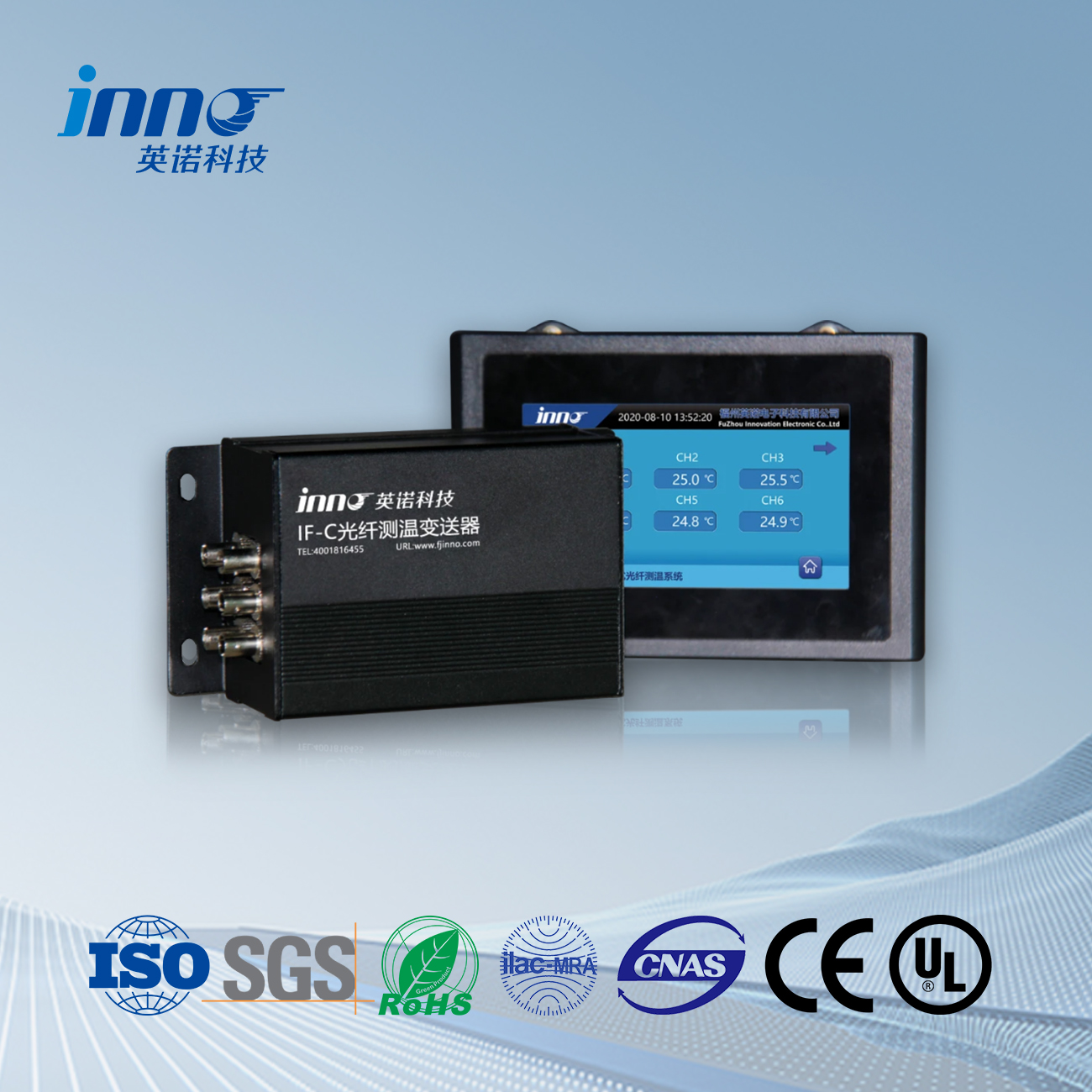
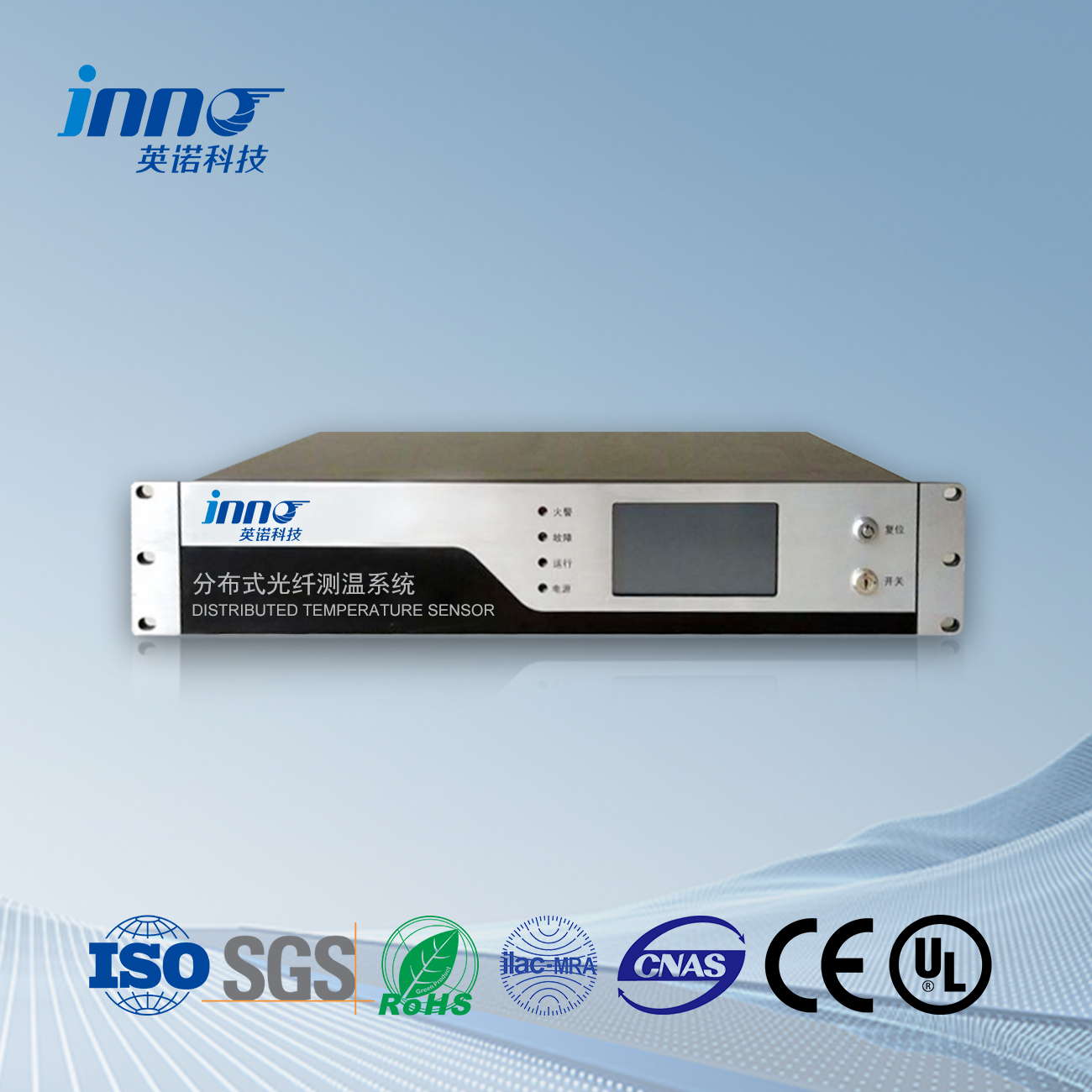
Real-Time Monitoring That Stops Problems Before They Start
Fiber optic sensors act as a 24/7 thermal watchdog for transformers, using hair-thin glass fibers to:
- Spot hidden hotspots – Detect temperature changes within 1°C accuracy
- Work in extreme conditions – No interference from oil, vibrations or lightning
- Cover every angle – Monitor 50+ points simultaneously inside the tank
Three-Step Overheating Defense System
When temperatures rise:
- Instant alerts at 90°C via control room dashboard
- Auto-cooling activation at 105°C (fans/oil pumps)
- Emergency shutdown if reaching 120°C
Proven Results: 80% Fewer Transformer Failures
In 28 power stations using this system:
- Average repair costs dropped by $5,000/year
- Unexpected outages reduced from 9 jotta 1 per year
- Transformer lifespan extended by 10-15 vuosia
Contents
- Fluorescent Decay Principle: Light-Based Thermal Tracking
- Direct Winding Contact Installation: Magnetic Probe Attachment
- High-Voltage Endurance: 550kV Insulation Performance
- Electromagnetic Immunity: Stable in Switchgear Operations
- Intrinsically Safe Design: Metal-Free Construction
1. Fluorescent Decay Principle: Light-Based Thermal Tracking
At the core of our system lies a phosphor-coated fiber tip that converts temperature into light signals. When embedded in transformer windings:
- Light pulses excite the fluorescent coating
- Decay rate measurement determines exact temperature
- Continuous mapping of 32 points per fiber strand
This method outperforms traditional RTDs by eliminating electrical interference risks. The glass fiber acts as both sensor and data highway, transmitting precise thermal profiles from deep within winding layers.
2. Direct Winding Contact Installation: Magnetic Probe Attachment
| Step | Tool | Time |
|---|---|---|
| Surface Prep | Alcohol wipe | 2 min |
| Sensor Mounting | Magnetic clamps | 5 min |
| Routing | Flexible conduit | 8 min |
Our epoxy-free installation allows permanent sensor placement during routine maintenance. A single monitoring unit supports up to 32 Kanavat, enabling full coverage of complex winding configurations without additional hardware.
3. High-Voltage Endurance: 550kV Insulation Performance
Designed for oil-immersed environments:
- Triple-layer silica coating withstands 150kV/mm fields
- Zero conductive components eliminate partial discharge
- Validated under IEC 60270 partial discharge tests
The fully insulated fiber path runs safely through bushing barriers, providing real-time data without compromising transformer integrity.
4. Electromagnetic Immunity: Stable in Switchgear Operations
During grid disturbances:
- Optical signals remain unaffected by magnetic fields
- Accurate readings during inrush current events
- No shielding required near CT/VT equipment
This immunity ensures reliable operation when conventional sensors fail – critical for capturing thermal data during fault conditions.
5. Intrinsically Safe Design: Metal-Free Construction
| Hazard | Traditional Risk | Our Solution |
|---|---|---|
| Spark Ignition | Metallic sensors | All-glass fiber |
| Corrosion | Copper elements | Chemical-resistant coating |
Ideal for explosive environments and corrosive oil mixtures, the system provides maintenance-free operation throughout the transformer lifecycle.
Trusted by Power Industry Leaders
As pioneers in optical sensing technology, we deliver:
- ▶️ Custom winding thermal models
- ▶️ On-site calibration services
- ▶️ 10-year performance warranty
“The fiber system detected abnormal heating six months before traditional alarms – potentially avoiding a $2M outage.”
– Senior Engineer, Grid Operations
Kuituoptinen lämpötila-anturi, Älykäs valvontajärjestelmä, Hajautettu kuituoptiikan valmistaja Kiinassa
 |
 |
 |
 INNO-valokuitulämpötila-anturit ,Lämpötilan valvontajärjestelmät.
