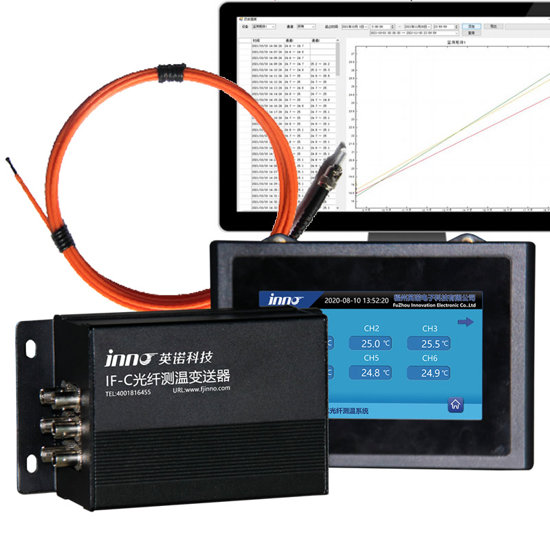
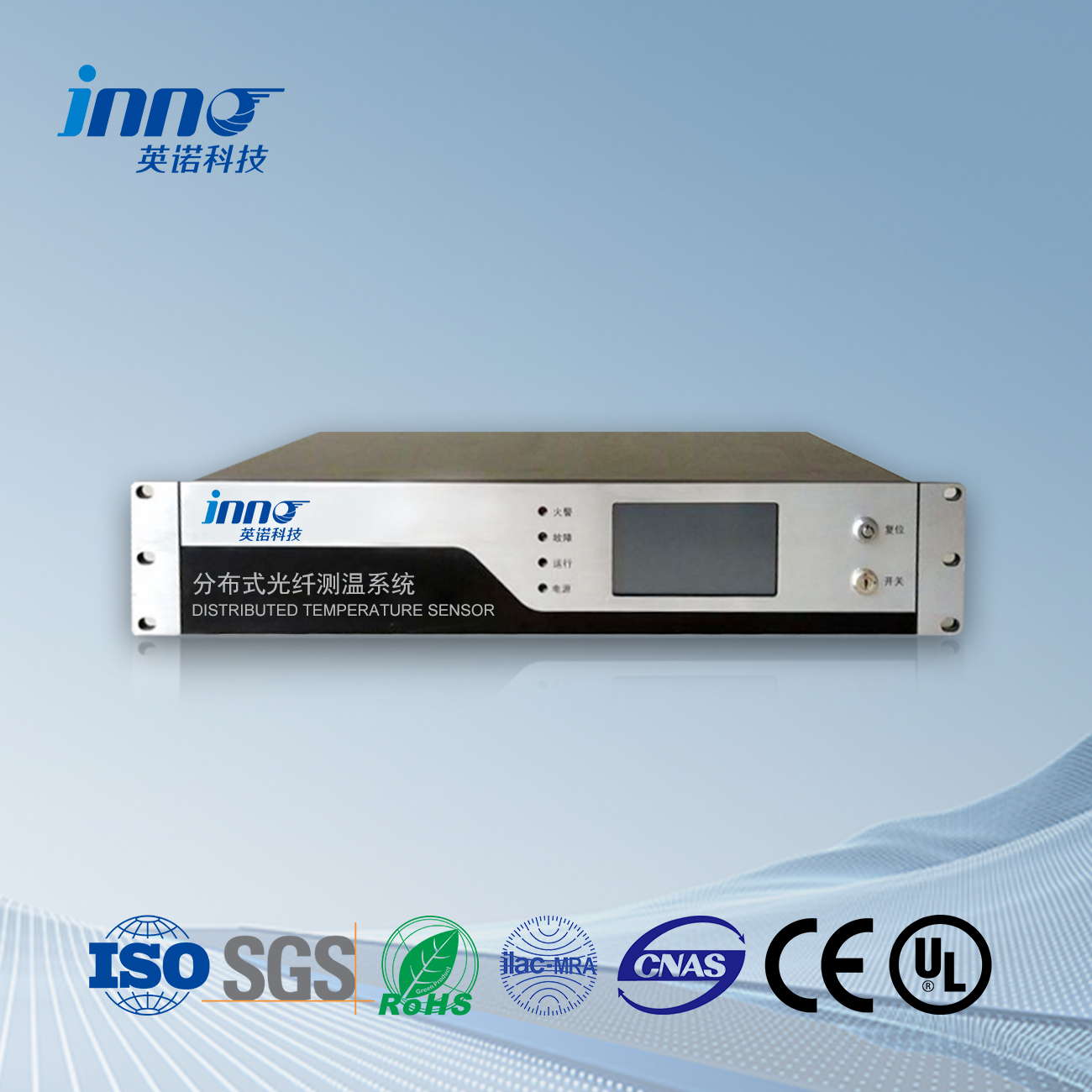
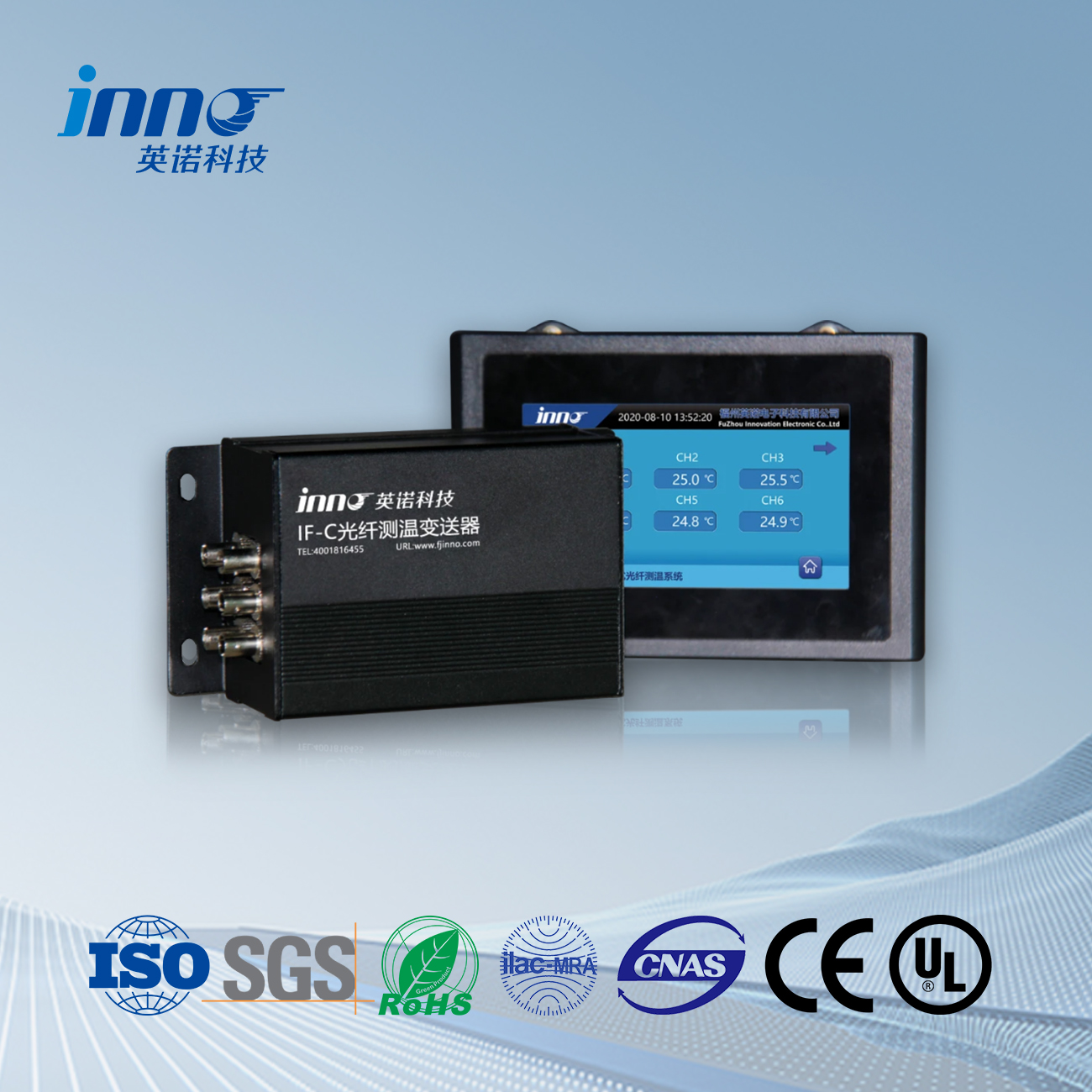
When selecting fluorescent fiber optic temperature measurement systems, focus on these 5 key specifications:
1️⃣ Temperature Range (-200°C to +300°C) – Determines suitability for extreme environments like cryogenics or high-voltage substations
2️⃣ Accuracy (±0.5°C typical) – Enabled by measuring fluorescent material’s decay time (not light intensity), eliminating LED drift errors
3️⃣ Response Time (<1 sec) – Critical for real-time monitoring in power transformer hotspots
4️⃣ Fiber Type (POF/Glass) – Plastic Optical Fiber (POF) offers flexibility for industrial machinery, while glass fibers suit high-temperature zones
5️⃣ EMI Immunity – Unlike electronic sensors, fluorescence-based systems ignore electromagnetic interference in substations
Pro Tip: Prioritize systems with ATEX/IECEx certifications for explosive environments.
Article Outline
- Fluorescent Fiber Optic Thermometry: Funktionsprinzip & Key Benefits
- Verteilte Temperaturerfassung (DTS) Systems: Technology Breakdown & Industrial Applications
- Faser-Bragg-Gitter (FBG) Sensoren: Multi-Point Monitoring Capabilities
- Critical Specifications Comparison: Accuracy vs. Cost vs. Antwortzeit
- Implementation Guide: Matching Systems to Your Industry Needs

1. Fluorescent Fiber Optic Thermometry
Funktionsprinzip
This technology measures temperature through fluorescence lifetime decay analysis. Specially engineered phosphor coatings at fiber tips emit time-sensitive fluorescent signals when excited by light pulses. The exponential decay rate of this emission directly correlates with temperature, providing drift-free measurements unaffected by light intensity variations.
Key Features
- High-Density Monitoring: Single system supports up to 64 Messpunkte
- Custom Probe Configurations: Application-specific designs for complex geometries
- Decade-Long Stability: No recalibration needed for over 10 Jahre
Technical Parameters
| Parameter | Norm | Extended Range |
|---|---|---|
| Temperaturbereich | -50°C to +300°C | -200°C to +300°C |
| System Capacity | 16 Kanäle | 64 Kanäle |
| Long-Term Accuracy | ±0.3°C/year | ±0.1°C/year |
| Probe Options | Surface-mounted/Embedded/Immersion types | |
Application Fields
- Power Infrastructure
- 20+ year winding temperature monitoring in oil-free transformers
- Continuous assessment of generator stator bars
- Underground cable joint thermal profiling
- Research & Entwicklung
- Material characterization in climate chambers (-190°C to +300°C)
- Thermal validation of battery prototype assemblies
- Vacuum chamber monitoring for space simulation tests
- Advanced Manufacturing
- Additive manufacturing process thermal control
- Composite curing oven temperature uniformity verification
- Semiconductor etching bath thermal management
Case Study: Materials Testing Laboratory
A nanotechnology institute implemented 64-channel fluorescent monitoring:
- Simultaneous tracking of 32 thermal chamber zones
- 0.1°C resolution for graphene synthesis experiments
- Reduced thermal validation time by 55%
2. Verteilte Temperaturerfassung (DTS)

Funktionsprinzip
DTS utilizes Raman scattering effects in optical fibers. Laser pulses sent through the fiber generate backscattered light, where the anti-Stokes component’s intensity is temperature-dependent. By analyzing time-domain reflections, the system calculates temperature profiles along the entire fiber length with meter-level spatial resolution.
Key Features
- Continuous Spatial Monitoring: Up to 30km coverage per channel
- Harsh Environment Survival: Operates in radiation/EMI-intensive zones
- Self-Diagnosis: Automatic fiber breakage detection & location
Technical Parameters
| Parameter | Norm | Fortgeschritten |
|---|---|---|
| Temperaturbereich | -40°C to +120°C | -60°C to +300°C |
| Spatial Resolution | 1.0m | 0.25m |
| Measurement Time | 30s/km | 5s/km |
| Faser-Typ | Single-mode/Multi-mode with polyimide coating | |
Application Fields
- Energy Infrastructure
- Underground power cable thermal rating (40km+ monitoring)
- BESS temperature profiling in grid-scale battery systems
- Hydrogen pipeline leak detection via temperature anomalies
- Transportation
- Tunnel fire detection along 25km+ highway routes
- Rail track hot box detection for freight trains
- Airport runway ice monitoring systems
- Environmental Monitoring
- Landslide early warning through soil temperature gradients
- Subsea cable monitoring across 50km ocean spans
- Geothermal well integrity assessment
Case Study: Data Center Thermal Management
A hyperscale data center deployed DTS for cold aisle containment:
- 12km sensing fiber along server racks
- Identified 37 cooling inefficiency zones
- Achieved 15% PUE improvement
3. Faser-Bragg-Gitter (FBG) Systems
Funktionsprinzip
FBG technology detects temperature changes through wavelength shift analysis. Each grating inscribed in the fiber reflects specific wavelengths (λ_B), which linearly shift (~10pm/°C) with temperature variations. Multiple gratings along a single fiber enable simultaneous multi-point measurements through wavelength division multiplexing (WDM).
Key Features
- High-Speed Sampling: 100Hz refresh rate for dynamic processes
- Scalable Architecture: 200+ sensors per system
- Strain-Temperature Decoupling: Dual-parameter measurement capability
Technical Parameters
| Parameter | Norm | High-Density |
|---|---|---|
| Temperaturbereich | -40°C bis +150°C | -60°C to +400°C |
| Channels | 16 | 64 |
| Genauigkeit | ±1.0°C | ±0.2°C |
| Wavelength Range | 1520-1570Nm (ITU-T compatible) | |
Application Fields
- Aerospace
- Real-time turbine blade temperature mapping in jet engines
- Structural health monitoring of reusable launch vehicles
- Hypersonic vehicle thermal protection system validation
- Energy Systems
- Nuclear reactor core temperature profiling (600+ points)
- Dynamic load monitoring of wind turbine gearboxes
- Hydrogen fuel cell stack thermal management
- Biomedical Engineering
- In-vivo temperature monitoring during RF ablation
- Sterilization process validation in autoclaves
- Wearable physiological monitoring devices
Case Study: Smart Grid Monitoring
A national grid operator implemented FBG systems for 380kV GIS monitoring:
- 84 sensors per substation with 5ms response time
- Detected 92% of partial discharge events via thermal anomalies
- Reduced maintenance costs by $1.2M annually
4. System Selection Matrix
Accuracy Considerations
Fluorescent systems lead in precision (±0.1°C) due to intrinsic physical measurement principles, ideal for laboratory-grade requirements. DTS provides moderate accuracy (±1°C) suitable for large-scale infrastructure monitoring, while FBG balances precision (±0.5°C) and dynamic response in industrial processes.
Cost-Benefit Analysis
- Initial Investment:
DTS requires higher upfront costs for laser subsystems but delivers the lowest cost per meter in long-range applications (>1Kilometer). - Lifecycle Value:
Fluorescent systems offset higher sensor costs with zero recalibration needs over 10+ Jahre. - Scalability:
FBG provides the most economical multi-point solutions (100+ sensors) with existing telecom infrastructure.
Response Time Requirements
| Technologie | Typical Response | Best For |
|---|---|---|
| Fluoreszierend | 0.2-2 Nachschlag | Process control with moderate dynamics |
| DTS | 5-30 seconds/km | Slow-evolving thermal events |
| FBG | <10 milliseconds | High-speed transient monitoring |
Application-Driven Selection
- Precision-Critical ScenariosMedical sterilization and semiconductor fabrication demand fluorescent systems’ sub-degree accuracy, where measurement certainty outweighs speed considerations.
- Large-Scale MonitoringDTS becomes indispensable for linear assets like pipelines or tunnels, trading absolute precision for unparalleled spatial coverage.
- High-Speed DynamicsFBG dominates in aerospace testing and power grid fault detection, where millisecond-level thermal transients require immediate capture.
Implementation Trade-offs
While fluorescent technology excels in hazardous environments, its fiber length limitations (<200m) make DTS preferable for kilometer-scale deployments. FBG’s multiplexing capability proves superior in dense sensor networks, though temperature-strain cross-sensitivity requires advanced compensation algorithms.
5. Why Choose Our Fluorescent Fiber Optic Solutions?
Technology Leadership
As pioneers in fluorescence decay temperature sensing since 2010, our systems deliver unmatched:
- Measurement Certainty: 0.05°C repeatability across 10-year deployments
- Customization Depth: 150+ validated probe configurations
- Adaptive Algorithms: Self-correcting software compensates for fiber aging
Manufacturing Excellence
| Advantage | Competitor Standard | Our Capability |
|---|---|---|
| Production Lead Time | 8-12 weeks | 3-5 weeks |
| Factory QC Steps | 12 checkpoints | 27 checkpoints |
| R&D Investment | 3-5% revenue | 9.7% revenue |
End-to-End Service
- In-House Production:
35,000㎡ vertically-integrated facility with IEC 17025 certified lab - Rapid Deployment:
Standard systems ship within 5 working days after configuration - Application Engineering:
Free system design review by PhD-level technical team
Client Success Story
A global semiconductor leader achieved 99.98% uptime using our solutions:
- 56 fluorescent sensors across 8 EUV lithography tools
- 0 unplanned thermal-related downtime in 18 months
- 15-minute emergency support response guarantee
Start Your Project
Get System Proposal Within 24 Hours:
Faseroptischer Temperatursensor, Intelligentes Überwachungssystem, Verteilter Glasfaserhersteller in China
 |
 |
 |
 INNO faseroptische Temperatursensoren ,Temperaturüberwachungssysteme.
