Power cables are the critical infrastructure that delivers electricity from generation sources to consumers. Their reliable operation is essential for maintaining a stable and functioning society. Cable failures can lead to widespread power outages, significant economic losses, and potential safety hazards. This article provides an in-depth look at advanced cable monitoring systems, focusing on how these technologies enhance power grid reliability and prevent costly failures. We will cover key monitoring techniques, including temperature monitoring, partial discharge (PD) detection, sheath current analysis, and AI-powered fault prediction, with a particular emphasis on the benefits of fiber optic sensing.
Table of Contents
- 1. Introduction: The Importance of Cable Monitoring
- 2. Key Parameters for Cable Monitoring
- 3. Specific Applications
- 4. System Integration and Data Management
- 5. Case Studies
- 6. Future Trends
- 7. Conclusion
1. Introduction: The Importance of Cable Monitoring
The modern power grid is a complex network of interconnected components, with power cables serving as the vital arteries that transport electricity over long distances. These cables are subjected to various stresses, including electrical, thermal, mechanical, and environmental factors. Aging infrastructure, increasing power demands, and the integration of renewable energy sources further exacerbate these stresses, making cable monitoring increasingly critical.
Traditional methods of cable maintenance, such as periodic inspections and offline testing, are often insufficient to detect incipient faults before they lead to major failures. These methods are time-consuming, labor-intensive, and may not provide a complete picture of the cable’s condition. Furthermore, they require taking the cable out of service, which can be disruptive and costly.
Key Takeaway: Moving from reactive or time-based maintenance to predictive maintenance, enabled by continuous condition monitoring, is essential for improving power grid reliability and reducing costs.
Cable monitoring systems offer a proactive approach to asset management. By continuously monitoring key parameters, these systems provide early warning signs of potential problems, allowing utilities to take corrective action *before* a failure occurs. This not only prevents costly outages but also extends the lifespan of valuable cable assets and enhances overall system safety.
2. Key Parameters for Cable Monitoring
Effective cable monitoring requires a comprehensive approach, focusing on several key parameters that provide insights into the cable’s health and performance. These parameters include:
2.1 Temperature Monitoring
Temperature is arguably the most critical parameter to monitor in power cables. Excessive temperature accelerates insulation degradation, leading to reduced lifespan and an increased risk of failure. The relationship between temperature and insulation life is often described by the Arrhenius equation, which demonstrates an exponential decrease in lifespan with increasing temperature.
Figure 1: Illustration of temperature distribution along a power cable, highlighting a potential hot spot.
Why is temperature monitoring so important?
- Preventing Thermal Runaway: Overheating can lead to thermal runaway, a positive feedback loop where increased temperature causes further increases in losses, leading to a rapid and uncontrolled temperature rise and eventual failure.
- Optimizing Cable Loading: Accurate temperature data allows utilities to safely maximize the utilization of their cable assets, operating them closer to their thermal limits without exceeding them.
- Detecting Hot Spots: Uneven temperature distribution can indicate localized problems, such as poor connections, damaged insulation, or external heat sources.
- Extending Cable Lifespan: Maintaining the cable within its optimal temperature range slows down the aging process and extends its operational life.
Several technologies are used for temperature monitoring in power cables:
2.1.1 Distributed Fiber Optic Sensing (DFOS)
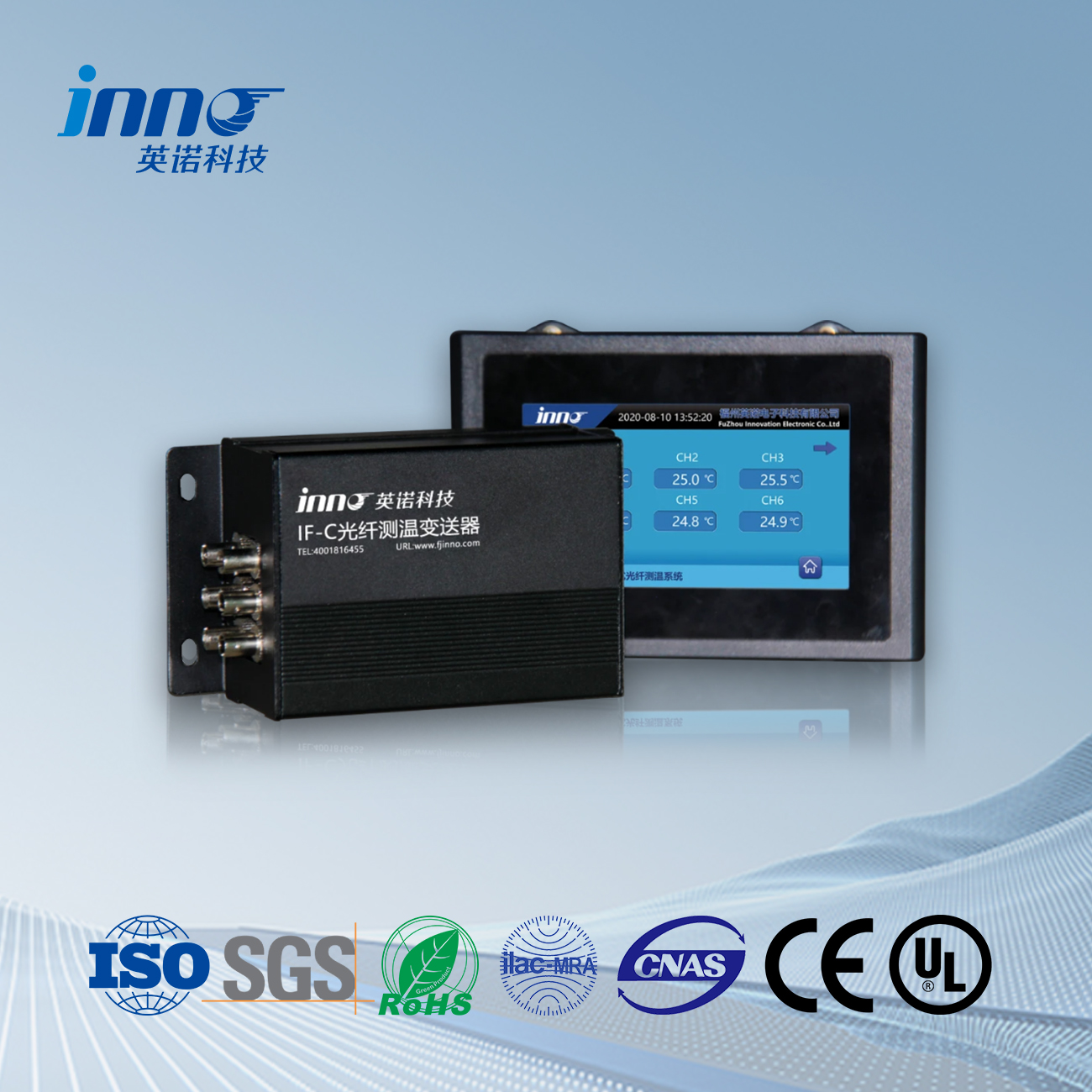
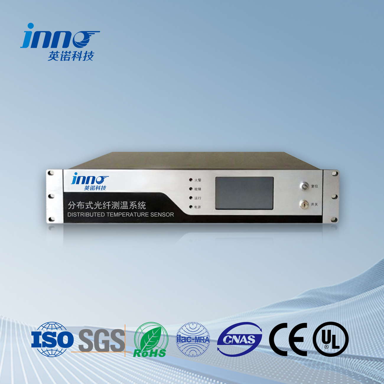
Distributed Fiber Optic Sensing (DFOS) is a revolutionary technology that transforms a standard optical fiber into a continuous temperature sensor. A pulse of light is launched into the fiber, and the backscattered light (Raman or Brillouin scattering) is analyzed. The characteristics of this backscattered light (intensity or frequency shift) change with temperature, allowing the system to determine the temperature at any point along the fiber. This provides a real-time temperature profile along the *entire* length of the cable.
- Raman Scattering: Measures the intensity ratio of Stokes and anti-Stokes components of the backscattered light. Suitable for shorter distances (up to a few tens of kilometers) with good temperature resolution (±1°C or better) and spatial resolution (down to 1 meter or less).
- Brillouin Scattering: Measures the frequency shift of the backscattered light. Suitable for very long distances (up to hundreds of kilometers) but with lower temperature resolution (±2-5°C) and spatial resolution (a few meters). Also sensitive to strain, requiring compensation techniques.
Advantages of DFOS:
- Continuous, real-time temperature profile.
- High spatial resolution.
- Long-range capability.
- Immunity to electromagnetic interference (EMI).
- Intrinsic safety (no electrical components in the sensing area).
Disadvantages of DFOS:
- Higher initial cost compared to point sensors.
- Requires specialized equipment (interrogators).
- Brillouin scattering requires strain compensation.
2.1.2 Fiber Bragg Grating (FBG) Sensors
Fiber Bragg Grating (FBG) sensors are another type of fiber optic sensor used for temperature monitoring. An FBG is a periodic variation in the refractive index of the fiber core. When light travels through the FBG, a specific wavelength (the Bragg wavelength) is reflected. This wavelength shifts with changes in temperature (and strain).
Multiple FBGs can be written onto a single fiber, allowing for *quasi-distributed* temperature sensing. Each FBG reflects a different wavelength, enabling the system to distinguish between them.
Advantages of FBG Sensors:
- High sensitivity and accuracy.
- Multiplexing capability (multiple sensors on a single fiber).
- Small size and lightweight.
- EMI immunity.
Disadvantages of FBG Sensors:
- Limited range compared to DFOS.
- Sensitive to both temperature and strain (requires compensation).
2.1.3 Fluorescence-Based Fiber Optic Sensors
Fluorescence-based fiber optic sensors utilize a special material (phosphor) at the fiber tip. When illuminated, it emits light (fluoresces) with a decay time that is directly proportional to temperature. These are particularly well-suited for monitoring the temperature of cable joints, which are critical points prone to overheating.
Advantages:
- High accuracy and stability.
- Immunity to EMI.
- Simple interrogation system.
Disadvantages:
- Point sensor, not distributed.
- Limited temperature range.
2.1.4 Traditional Point Sensors (Thermocouples, RTDs)
While fiber optic sensors are increasingly preferred, traditional point sensors like thermocouples and Resistance Temperature Detectors (RTDs) still have applications in cable monitoring, particularly in retrofitting existing installations or where cost is a primary concern. However, they require wiring and are susceptible to EMI.
2.2 Partial Discharge (PD) Monitoring
Partial Discharge (PD) is a localized electrical discharge that occurs within insulation defects. It’s a leading indicator of insulation degradation and can lead to complete failure. PD monitoring systems detect and analyze these discharges to assess the condition of the insulation.
2.2.1 Ultra-High Frequency (UHF) Method
The UHF method detects electromagnetic waves emitted by PD in the UHF range (300 MHz – 3 GHz). UHF sensors (antennas) are installed inside the GIS enclosure or on dielectric windows (for gas-insulated switchgear) or at joints and terminations for cables. The UHF method is highly sensitive and can locate the PD source.
2.2.2 Acoustic Emission (AE) Method
The AE method detects ultrasonic sound waves generated by PD. Acoustic sensors (piezoelectric transducers) are attached to the outside of the cable or GIS enclosure. The AE method is less sensitive than UHF but can be useful for locating PD in specific areas.
2.2.3 High-Frequency Current Transformer (HFCT) Method
The HFCT method measures high-frequency current pulses associated with PD. HFCTs are clamped around the grounding connection of the cable or GIS equipment.
2.2.4 Transient Earth Voltage (TEV) Method
The TEV method measures the transient voltage pulses on the cable sheath or metallic enclosure that are induced by PD activity inside.
2.3 Sheath Current Monitoring
Induced currents in the cable sheath can indicate sheath faults, bonding problems, or uneven load distribution. Excessive sheath currents can lead to overheating and damage. Current transformers (CTs) or Rogowski coils are used to measure the sheath current.
2.4 Fault Prediction and Localization
The ultimate goal of cable monitoring is to predict and prevent failures. Advanced data analysis techniques, including trend analysis, pattern recognition, and Artificial Intelligence (AI) / Machine Learning (ML), are used to identify anomalies and predict impending faults. Time-Domain Reflectometry (TDR) and DFOS (Brillouin scattering) are used for fault localization.
3. Specific Applications
Cable monitoring systems are deployed in various applications, including:
- Underground power cables
- Submarine power cables
- High-voltage direct current (HVDC) cables
- Cable joints and terminations
- Wind turbine cables
- Railway cables
- Mining cables
4. System Integration and Data Management
A comprehensive cable monitoring system includes data acquisition units (DAUs), communication networks (fiber optic, wireless, or cellular), data storage and processing servers, and visualization and reporting software. Integration with SCADA systems is often crucial for overall power system management.
5. Case Studies
(This section would include real-world examples of successful cable monitoring system deployments, demonstrating the benefits achieved, such as prevented outages, reduced maintenance costs, and extended asset life. Each case study should be detailed and specific.)
Example Case Study Outline (to be expanded):
- Project Title: Preventing Submarine Cable Failure with DFOS
- Client: [Name of Utility or Company]
- Challenge: A long submarine power cable was at risk of damage from anchor strikes and seabed movement. Traditional inspection methods were costly and infrequent.
- Solution: A DFOS system based on Brillouin scattering was installed to continuously monitor temperature and strain along the entire cable length.
- Results: The system detected a gradual increase in strain at a specific location, indicating potential damage. Early detection allowed the utility to schedule a repair *before* a complete failure occurred, saving millions of dollars in repair costs and preventing a prolonged outage. The system also provided valuable data on cable movement and thermal stress, enabling better asset management.
6. Future Trends
The future of cable monitoring will see increased use of AI and ML, integration of multiple sensing technologies, development of self-powered sensors, cloud-based monitoring platforms, and standardization of communication protocols.
7. Conclusion
Cable monitoring systems are essential for ensuring the reliable and efficient operation of power grids. By leveraging advanced technologies like DFOS, FBG, and PD monitoring, utilities can proactively identify and address potential problems *before* they lead to costly failures. The shift from reactive to predictive maintenance, enabled by continuous condition monitoring, is transforming asset management and improving the resilience of critical infrastructure. As the power industry continues to evolve, cable monitoring will play an increasingly vital role in ensuring a secure and sustainable energy future. Companies specializing in these technologies, particularly those with expertise in fiber optic sensing and custom solutions, are well-positioned to meet the growing demands of the industry.
Fiber optic temperature sensor, Intelligent monitoring system, Distributed fiber optic manufacturer in China
 |
 |
 |
 INNO fibre optic temperature sensors ,temperature monitoring systems.
