Principle of Fluorescent Fiber Optic Technology for Monitoring Hot Spot Temperature of Dry type Transformers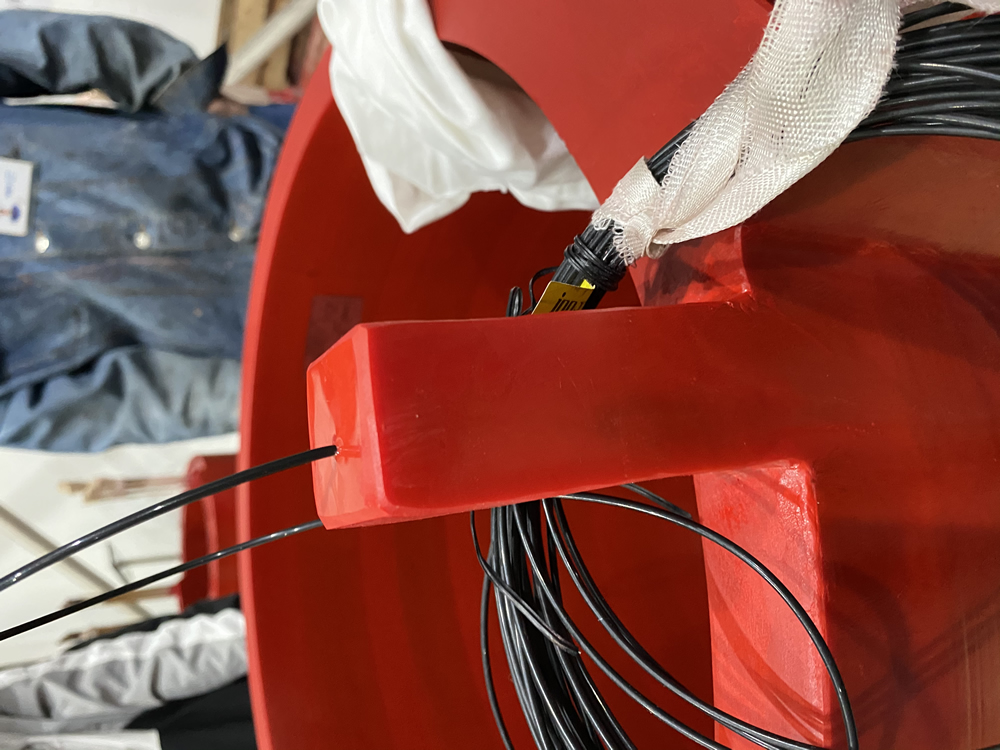
The basic principle of using fluorescent fiber optic sensor technology for hot spot temperature monitoring of dry-type transformers is to utilize the temperature characteristics of fluorescent substances. Специално, the fluorescence medium is excited by blue violet light to produce fluorescence, and the lifetime of the fluorescence decreases with increasing temperature. Следователно, temperature measurement can be achieved by detecting the lifetime of the fluorescence.
When fluorescent materials are irradiated with excitation light, they emit fluorescence, which usually decays exponentially. The decay time constant is the fluorescence lifetime or fluorescence afterglow time (ns). The decay of fluorescence afterglow varies at different environmental temperatures. The detector can accurately measure the ambient temperature of the probe and provide monitoring and alarm by measuring the length of the fluorescence afterglow lifetime.
This temperature measurement method has some unique advantages, such as being a passive temperature measurement method, and due to the fully insulated and small size of the fiber optic temperature sensor, it can directly measure the highest temperature of the internal hotspots that are prone to occur in high-voltage electrical equipment. Meanwhile, the characteristics of fluorescent materials enable this technology to have high accuracy and stability in measuring temperature.
1. Method of using fluorescent optical fiber to monitor the hot spot temperature of dry-type transformers
1.1 Installation of sensors
Choose the appropriate installation location
For dry-type transformers, fiber optic sensors can be installed in internal heat sinks, windings, and other areas that are prone to hot spots. The winding generates heat during the operation of the transformer. If the heat dissipation is poor or the load is too high, hot spots will appear on the winding. The heat sink is a component specifically designed for heat dissipation, and monitoring its temperature can also help understand the heat dissipation condition of the transformer.
During installation, it is necessary to ensure that the sensor can accurately reflect the hot spot temperature. Например, when installing on the winding, the structure and current distribution of the winding should be considered, and the sensor should be installed at the location where the highest temperature may occur.
1.2 Installation method and precautions
The installation of sensors should ensure good contact with the measured area to ensure accurate temperature sensing. For the windings of dry-type transformers, it may be necessary to pre-set the installation position during manufacturing or maintenance to avoid damage to the windings during the installation process.
When installing optical fibers, it is important to note that the bending radius of the fiber should not be too small, as the optical loss caused by fiber bending can affect the calculation of the attenuation time constant, thereby affecting the accuracy of temperature measurement. В същото време, it is necessary to avoid excessive stretching or compression of the optical fiber to prevent damage.
2. Data collection and processing
2.1 Signal acquisition
Use specialized equipment to collect signals emitted by fluorescent fiber optic sensors. During this process, excitation light will be directed onto the fluorescent substance, and then the fluorescence afterglow signal will be detected. The collection equipment needs to have high sensitivity and accuracy to capture weak fluorescence signal changes.
Due to the possibility of installing fluorescent fiber optic sensors at different locations inside transformers, corresponding wiring and signal transmission channels are required to transmit the signals from each sensor to the acquisition equipment.
2.2 Data Processing
The collected fluorescence afterglow signal needs to be processed to obtain the temperature value. According to the relationship curve between fluorescence lifetime and temperature (which is usually obtained through pre calibration), convert the measured fluorescence afterglow decay time into temperature values.
In the process of data processing, possible error factors such as insertion loss at fiber optic joints and optical loss of external optical cables should be considered to improve the accuracy of temperature measurement by compensating for them through algorithms.
3. Composition and operation of monitoring system
3.1 System composition
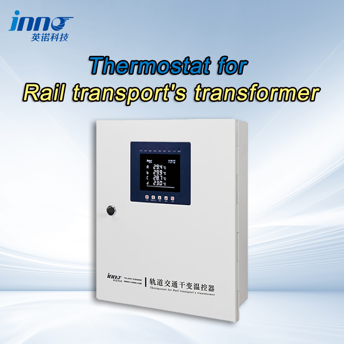
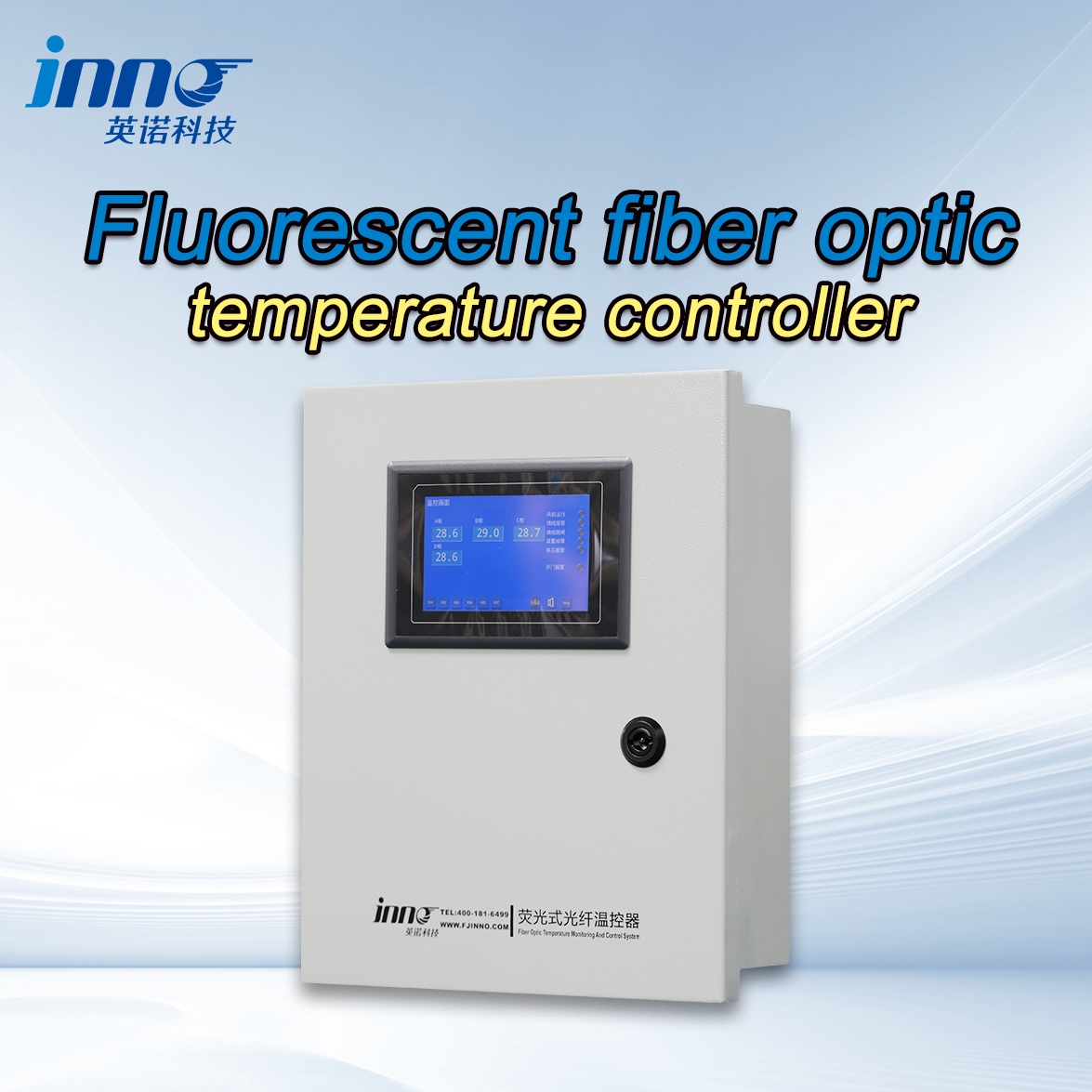
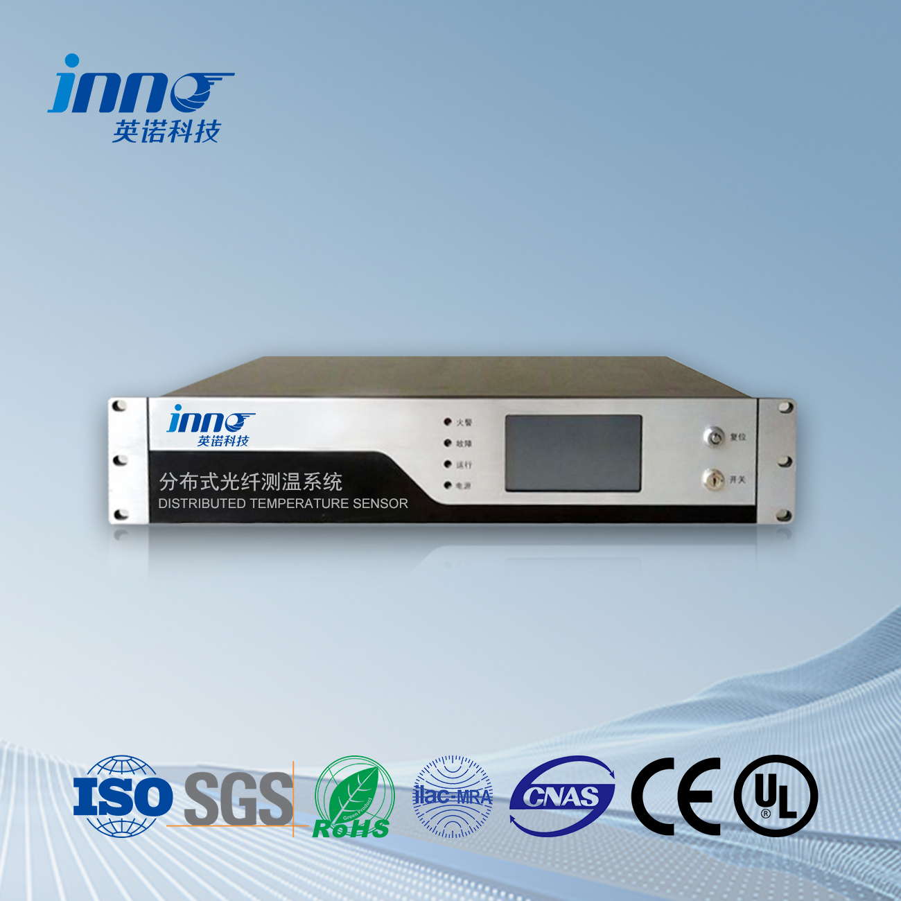
The dry-type transformer fluorescent fiber optic hot spot temperature monitoring system mainly consists of fluorescent fiber optic temperature sensors, signal acquisition devices, data processing units, display and alarm devices, and other parts.
As the front-end component for temperature measurement, В fluorescent fiber optic temperature sensor is responsible for sensing temperature and converting temperature information into fluorescence signal changes. The signal acquisition device collects the fluorescence signal emitted by the sensor, and the data processing unit analyzes and processes the collected signal, converting it into a temperature value. The display device is used to display real-time temperature data of each monitoring point, while the alarm device issues an alarm when the temperature exceeds the set threshold.
3.2 System Operation
During the operation of the system, it is necessary to regularly inspect and maintain the sensors and the entire monitoring system. Ensure that the sensors are functioning properly, signal transmission is smooth, and data processing is accurate. В същото време, adjust the parameters of the monitoring system, such as alarm thresholds, based on the operating status and environmental conditions of the transformer.
2. Application case of fluorescent optical fiber in hot spot temperature monitoring of dry-type transformers
2.1. Improve the operational safety of dry-type transformers
Real time monitoring of hotspot temperature
In the distribution room of a large industrial enterprise, dry-type transformers play an important role in power supply. Due to the complex environment of the distribution room and the presence of certain electromagnetic interference, traditional temperature monitoring methods are difficult to meet the requirements of accurate monitoring. After adopting a fluorescent fiber optic temperature measurement system, the fluorescent fiber optic sensor is installed in key parts such as the winding and heat sink of the dry-type transformer. By monitoring the hot spot temperature of these parts in real time, operation and maintenance personnel can timely grasp the operating status of the transformer. When the temperature of a certain part rises abnormally, the system can quickly issue an alarm to avoid transformer failure caused by overheating, ensuring the safety of power supply in the entire distribution room.
Prevent potential malfunctions
For some dry-type transformers that have been running for a long time, the insulation material inside may gradually age, leading to an increased risk of local overheating. In a substation renovation project in an old residential area, a fluorescent fiber optic hotspot temperature monitoring system was installed. Through long-term monitoring of the hot spot temperature of the transformer, several potential overheating points were discovered. After inspection, it was found that they were caused by loose connection points and insulation aging. After taking timely measures for repair, possible transformer failures were avoided and the service life of the transformer was extended.
2.2. Optimize the load management of dry-type transformers
Adjust the load according to the temperature
In the power supply system of data centers, the load of dry-type transformers fluctuates with the operating status of servers. Real time monitoring of the hot spot temperature of transformers through a fluorescent fiber optic temperature monitoring system. When the temperature approaches the set upper limit, management personnel can take measures to reduce the load on the transformer, such as adjusting the power allocation of the server or turning on the backup transformer to share the load. This ensures the safe operation of the transformer and improves the reliability of the entire data center’s power supply.
2.3 Evaluation of Transformer Load Capacity
In the power system of a commercial complex, long-term monitoring data of the hot spot temperature of dry-type transformers can be analyzed to evaluate the temperature changes of transformers under different load conditions. Based on these data, the maximum load capacity of the transformer is reasonably determined, the power distribution plan is optimized, and the transformer is avoided from being in an overloaded state for a long time, thereby improving the operational efficiency of the power system.
3. Precautions for Temperature Monitoring of Fluorescent Fiber Optic Hotspots in Dry type Transformers
3.1 Impact of Environmental Factors
electromagnetic interference
During the operation of dry-type transformers, there is an electromagnetic field around them. Although fluorescent fiber optic sensors themselves have a certain immunity to electromagnetic interference, attention should still be paid in practical applications. Например, in places with complex electromagnetic environments such as substations, it is necessary to ensure the electromagnetic compatibility of sensors and monitoring systems. In system design, shielded cables are used to transmit signals, and sensors and monitoring equipment are well grounded to prevent electromagnetic interference from affecting the collection and processing of fluorescence signals, thereby ensuring the accuracy of temperature measurement.
Humidity and dust
If the dry-type transformer is located in an environment with high humidity or dust, it may affect the performance of the fluorescent fiber optic sensor. Humidity may cause condensation on the surface of optical fibers, affecting the transmission of light; Dust may adhere to the surface of optical fibers, causing an increase in optical loss. Следователно, for sensors installed in such environments, protective measures need to be taken, such as using sealed protective enclosures and regularly cleaning the sensors and optical fibers.
3.2 Installation and maintenance of optical fibers
Fiber bending and loss
When installing optical fibers, it is necessary to strictly control the bending radius of the fibers. Excessive bending can cause scattering and loss of light inside the optical fiber, affecting the transmission and detection of fluorescence signals. Generally speaking, the bending radius of optical fibers should be greater than their minimum allowable bending radius, and the specific value depends on the type and specifications of the fiber. During the wiring process, it is important to avoid squeezing or scratching the optical fibers with sharp objects to prevent signal interruption caused by fiber damage.
Processing of fiber optic connectors
The quality of fiber optic connectors has a significant impact on signal transmission. When connecting optical fibers, it is necessary to ensure that the connectors are firmly connected and clean the fiber optic connectors to prevent dust, oil, and other pollutants from entering the connectors, which can increase the insertion loss of light. Regularly check the condition of fiber optic connectors, and repair or replace them promptly if they are loose or damaged.
3.3 Calibration and Accuracy of Sensors
Regular calibration
The accuracy of fluorescent fiber optic sensors will drift with changes in time and usage environment. To ensure the accuracy of temperature measurement, it is necessary to calibrate the sensor regularly. The calibration method is to place the sensor in an environment with a known temperature (such as a constant temperature chamber), measure its fluorescence afterglow lifetime, and compare it with the theoretical value at standard temperature. Adjust the parameters of the sensor to make its measured value match the actual temperature. The calibration cycle depends on factors such as the frequency of sensor usage and environmental conditions, and it is generally recommended to perform calibration every six months to one year.
Accuracy verification
During the installation and use of sensors, their measurement accuracy should be verified. Comparative measurement methods can be used, such as installing fluorescent fiber optic sensors and other temperature sensors with known accuracy (such as thermocouples) simultaneously on dry-type transformers, and comparing the temperature values measured by the two sensors under different loads and operating conditions. If the deviation between the two exceeds the allowable range, it is necessary to inspect and adjust the fluorescent fiber optic sensor.
4. Method for optimizing the temperature monitoring effect of fluorescent fiber hotspots in dry-type transformers.
4.1 Optimization of Sensor Layout
Accurate positioning of hotspot areas
Conduct in-depth analysis of the heating principle and structure of dry-type transformers, and identify key areas where hotspots may occur. Например, fluorescent fiber optic sensors should be placed in places where heat accumulation is likely to occur, such as between turns, between layers, and at the connection between the winding and the iron core. Through precise sensor layout, the hot spot temperature of transformers can be monitored more comprehensively and accurately, avoiding the omission of important hot spots.
Reasonable determination of the number of sensors
Reasonably determine the number of fluorescent fiber optic sensors based on factors such as the capacity, voltage level, and heat dissipation method of dry-type transformers. For transformers with large capacity, high voltage levels, or poor heat dissipation conditions, the number of sensors can be appropriately increased to obtain more detailed temperature distribution information. But at the same time, cost and system complexity should also be considered to avoid excessive sensor waste and increased difficulty in system maintenance.
4.2. Improve the performance of the monitoring system
Adopting high-precision sensors and acquisition devices
Choosing a fluorescent fiber sensor with higher sensitivity and lower drift can improve the accuracy of temperature measurement. In terms of signal acquisition, high-precision acquisition equipment such as photodetectors with high resolution and low noise can more accurately capture subtle changes in fluorescence signals. These high-precision devices can effectively reduce measurement errors and improve the performance of the entire monitoring system.
Optimize signal transmission and processing algorithms
For the problem of signal attenuation during fiber optic transmission, signal enhancement techniques such as optical amplifiers can be used to increase the strength of the signal. In terms of data processing, developing more advanced algorithms, such as real-time compensation algorithms for fiber loss, fluorescence signal attenuation, и така нататък., can improve the accuracy and stability of temperature measurement. Meanwhile, optimizing the data filtering algorithm to remove noise interference makes the measurement results more reliable.
4.3 Strengthen system maintenance and management
Regular maintenance plan
Develop a detailed regular maintenance plan, including inspection and maintenance of fluorescent fiber optic sensors, signal acquisition equipment, data processing units, и така нататък. Например, regularly cleaning sensors and fiber optic surfaces, checking the connection of fiber optic connectors, and conducting functional tests on equipment. Through regular maintenance, potential problems can be identified and resolved in a timely manner, ensuring the normal operation of the monitoring system.
Remote monitoring and fault diagnosis
Establish a remote monitoring system to enable operation and maintenance personnel to remotely view real-time hot spot temperature data of dry-type transformers. В същото време, a fault diagnosis function is added to the system, which can automatically diagnose possible faults such as sensor failures, signal transmission interruptions, и така нататък. by analyzing temperature data and monitoring the system’s own status, and promptly notify operation and maintenance personnel for handling. This can improve operational efficiency and reduce the time required for fault repair.
Оптичен температурен сензор, Интелигентна система за мониторинг, Производител на разпределени оптични влакна в Китай
 |
 |
 |
 Оптични температурни сензори INNO ,Системи за мониторинг на температурата.
