Fiberoptisk temperatursensor, Intelligent overvåkingssystem, Distribuert fiberoptisk produsent i Kina
 |
 |
 |
Fiberoptisk temperaturmålingssystem for koblingsanlegg
1. Installation scale.
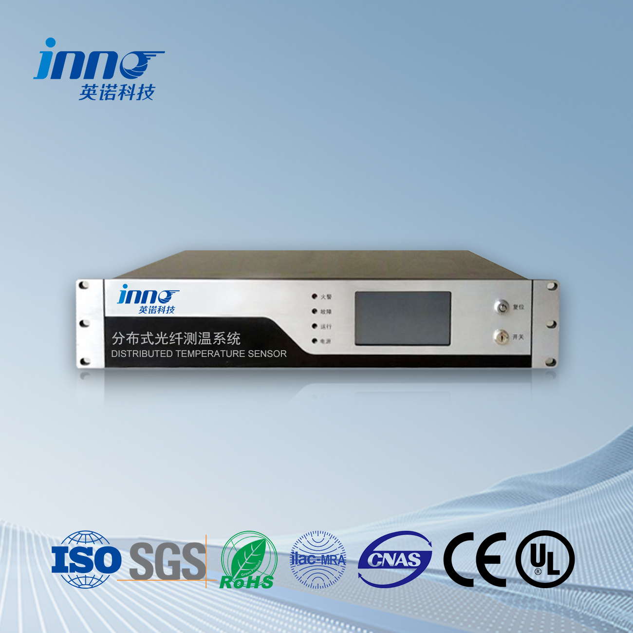
Select the 10kV high-voltage switchgear of a certain substation as the main monitoring object of the monitoring system. Blant dem, the laying of temperature measuring optical fibers is carried out inside the N circuit 10kV outgoing high-voltage switchgear (the number of intervals can be freely selected according to the requirements of the power grid), and 9 key heating points are set in each outgoing high-voltage switchgear; Lay temperature measuring optical fibers inside the 10kV incoming high-voltage switchgear, with a total of 12 key heating points set up; The laying of temperature measurement optical fibers is carried out inside the 10kV segmented high-voltage switchgear and isolation high-voltage cabinet, with a total of 12 key heating points set up. The monitoring system is equipped with one high-performance industrial computer as the local temperature measurement workstation in the main control room of the substation, one temperature measurement host with 2-way fiber optic switching, and two 2-way 2-kilometer temperature measurement fiber optic cables.
2. Installation form:
① The laying of optical fibers. The temperature measurement optical fiber of the monitoring system is laid parallel to the cable trench and fixed with thermal conductive silicone or other insulation fixtures.
② Fiber optic temperature measurement of cable heads. For temperature measurement of cable heads, installation is carried out in the form of fiber optic coils to ensure the accuracy of temperature measurement and positioning of hot spots. The optical fiber should be insulated and sheathed with a diameter of 0.9 millimeters and resistance to temperature interference. Metal armored optical fibers should not be used, and the optical fiber should be fixed by screws.
③ Temperature measurement of the dynamic and static contacts of the switchgear. 10kV switchgear is mostly a sealed structure, but it is not completely sealed inside and can be installed with optical fibers. In order to facilitate switch maintenance and avoid damage to the optical fiber, the optical fiber should not be installed in movable or collision prone parts, but should be installed at the static contact, which will not affect the measurement accuracy and temperature accuracy of the tested part. Fiber optic installation involves completely laying one switchgear before moving to another switchgear. The installation inside the cabinet can be done using cross phase installation method or nearby installation method. Due to the good insulation performance of optical fibers, and the fact that 10kV switchgear is mostly a fully enclosed structure, its dust resistance is good and it will not cause phase to phase faults. The frameless optical fiber is wound and installed at the static contact, and pasted with thermal conductive silicone.
3. Software settings for switchgear temperature measurement system.
According to the operating regulations of the substation and the characteristics of the high-voltage switchgear, calculate the length of the optical fiber, set basic information for key temperature measurement points, and alarm temperature values. Due to the fact that the fault monitoring system is not connected to the control circuit, the trip temperature has not been set, and the overheat alarm temperature is set at 30 °C.
4. The application of Fiberoptisk temperaturmåling in enclosed switchgear
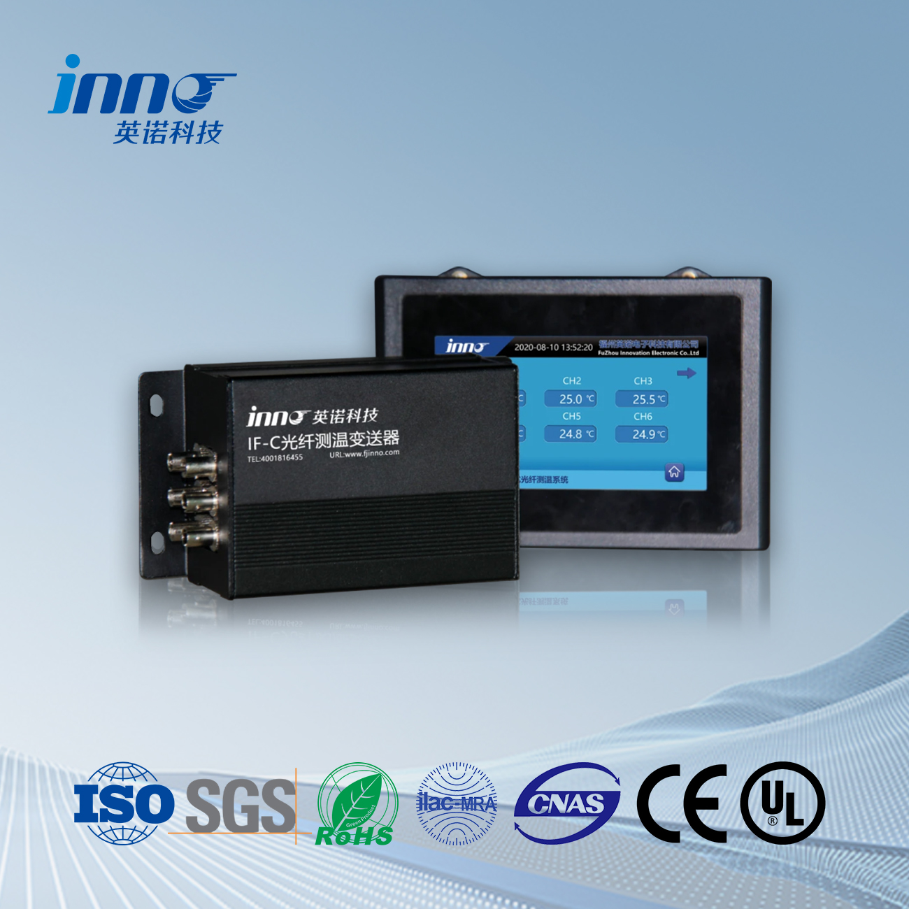
The temperature numerical monitoring instrument for switchgear utilizes the principle of backscattering generated by laser transmission in optical fibers to achieve online temperature detection of electrical equipment. The advanced monitoring system realizes early prediction of overheating faults, laying the foundation for condition maintenance.
It is believed that the application of fault monitoring systems in substations, especially in enclosed switchgear, has solved the problem of long-term inability to measure temperature at the joints of this type of equipment in terms of transmission, transformation, distribution, and power safety. Real time online temperature monitoring is carried out on the internal switch contacts, TA joints, cable joints, etc. of the enclosed switchgear using a monitoring system, and abnormal monitoring information is transmitted to the centralized monitoring center through local area network channels at any time, achieving effective monitoring of the operating status of internal equipment in the switchgear, eliminating accidents caused by heating of internal switch contacts, TA joints, cable joints, etc., and ensuring the safe and stable operation of the power system.
 INNO fiberoptiske temperatursensorer ,Systemer for temperaturovervåking.
